
Lamp Dimmers

The circuit described is indicative of a basic electronic design that lacks certain filtering components, notably a choke, which is essential for reducing electromagnetic interference. The absence of a choke can lead to substantial RFI, which may affect nearby electronic devices and communication systems. The design's reliance on house wiring to limit di/dt suggests that it is intended to operate within typical residential electrical parameters, utilizing the inherent inductance of the wiring to mitigate rapid changes in current.
The mention of hysteresis at dim settings indicates that the circuit may employ a feedback mechanism that stabilizes the output brightness against fluctuations in input voltage or load conditions. This hysteresis can be beneficial in preventing flickering or instability at lower brightness levels but may also introduce undesirable effects if the feedback is not properly designed.
Furthermore, the statement about the quality of consumer products implies that this design may be a low-cost solution that sacrifices performance for affordability. Such designs may be prevalent in low-end consumer electronics where cost constraints take precedence over performance optimization. The implications of this can lead to a user experience that is less than satisfactory, particularly in environments sensitive to RFI.
In summary, the circuit's design, while economical, may not meet the expectations of users looking for high-quality performance, especially in applications where RFI is a concern. Proper circuit design would typically include additional components such as chokes, capacitors, and possibly shielding to enhance performance and reduce interference.This must generate an awfull lot of RFI without a choke! The house wiring supplies the di/dt limiting. This is a CHEAP design which exhibits hysterisys at dim settings. Not everything made and sold to the public is top notch. 🔗 External reference
Related Circuits
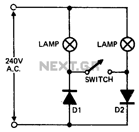
When setting up photographic floodlamps, it is sometimes desirable to operate the lamps at lower power levels until actually ready to take the photograph. The circuit allows the lamps to operate on half-cycle power when the switch is open...
For several years, a rear fog lamp has been mandatory for trailers and caravans to enhance visibility in foggy conditions. When the fog lamp is activated, the fog lamp of the towing vehicle must be turned off to prevent...
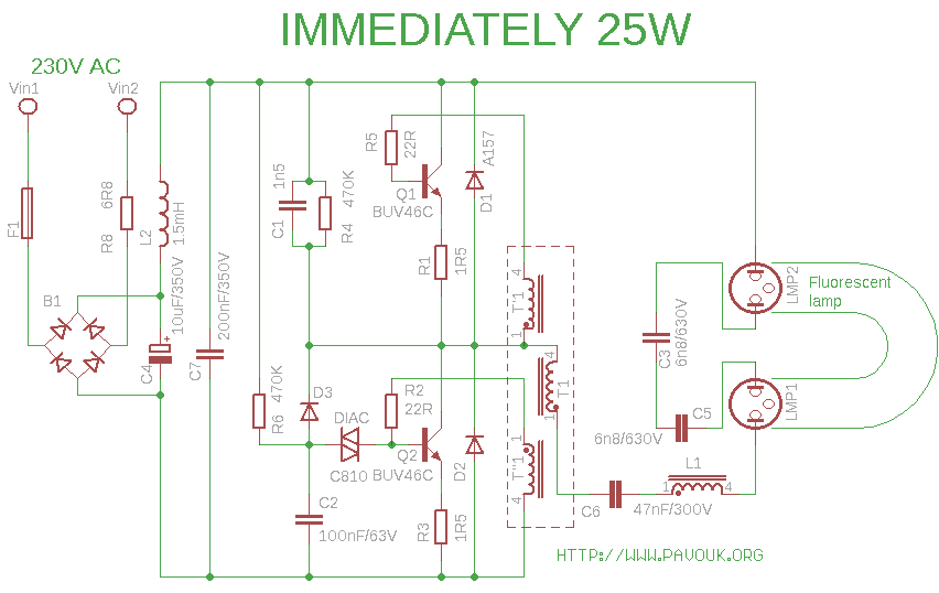
Compact fluorescent lamps offer several advantages over traditional incandescent bulbs, including reduced power consumption (up to 80%) and significantly longer lifespans (5 to 15 times longer). However, they have some drawbacks, such as longer warm-up times, particularly in more...
This circuit is a 73 MHz halogen lamp radio-controlled system. Its purpose is to control the power state of a halogen lamp using a remote control. When the push button on the remote control is pressed, the power state...
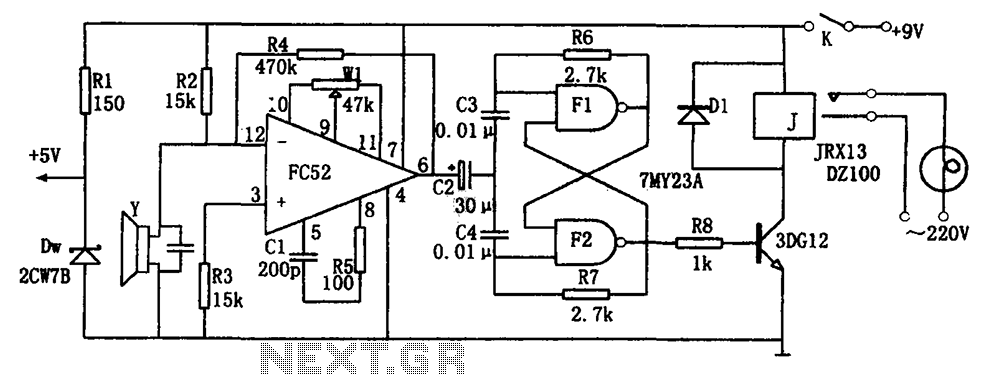
The voice-activated lamp circuit consists of an operational amplifier FC52, a flip-flop made from two NAND gates TMY23A, a relay J, a piezoelectric crystal speaker Y, and additional components. The flip-flop processes the sound signal from the speaker, converting...

The Joule thief has been previously discussed in various forums, and while the concept is not new, this version incorporates additional information and testing data. The circuit schematic includes a 2N4401 transistor and a small toroid. The Joule thief is...