
Floodlamp power control

The described circuit is designed for controlling the power output to photographic floodlamps, providing flexibility in operation mode. In the open switch state, the circuit operates in half-cycle mode, effectively reducing the power supplied to the lamps. This is particularly useful during setup, allowing users to adjust positioning and lighting without exposing the photographic subject to full intensity light. When the switch is closed, the circuit transitions to full power mode, enabling the floodlamps to emit their maximum brightness for the actual photography.
The circuit employs two diodes, D1 and D2, which are critical for rectifying the AC supply to the floodlamps. The specified diodes must have a peak inverse voltage (PI-V) rating of at least 400 volts to withstand the voltage spikes that may occur in the circuit. Additionally, they should be rated for a forward current of 5 amps to ensure they can handle the operational current without overheating or failing.
The switch used in the circuit should be rated for the same voltage and current levels to ensure safe operation. The design may also include fuses or circuit breakers to protect against overload conditions. Proper heat dissipation measures, such as heat sinks for the diodes, may be necessary to maintain reliability and longevity of the components.
Overall, this circuit design provides a practical solution for photographers requiring control over their lighting setup, ensuring both versatility and safety during the operation of high-intensity floodlamps.When setting up photographic floodlamps, it is sometimes desirable to operate the lamps at lower power levels until actually ready to take the photograph. The circuit allows the lamps to operate on half cycle power when the switch is open, and full power, when the switch is closed
The diodes D1 and D2 should have a 400 volt PI-V rating at 5 amps.
Related Circuits
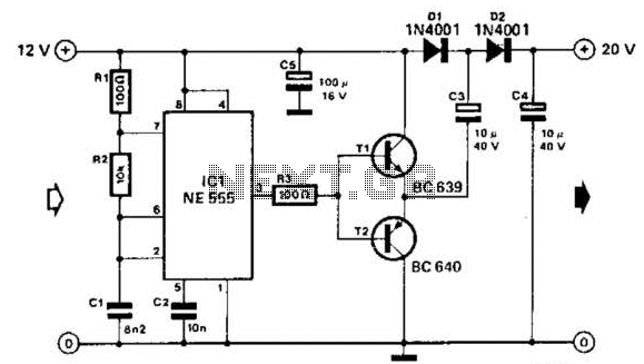
Using a 555 timer and voltage doubler, this circuit will supply over 50 mA at 20 V DC. Transistors T1 and T2 act as power amplifiers to drive the voltage doubler. The frequency of operation is approximately 8.5 kHz. The...
An infrared wired repeater circuit is designed to control appliances from a remote location. Parts List: R1: 1k Resistor (1), R2: 3.3k Resistor (1), R3: 10k Resistor (1). The infrared wired repeater circuit serves as an interface for controlling various...
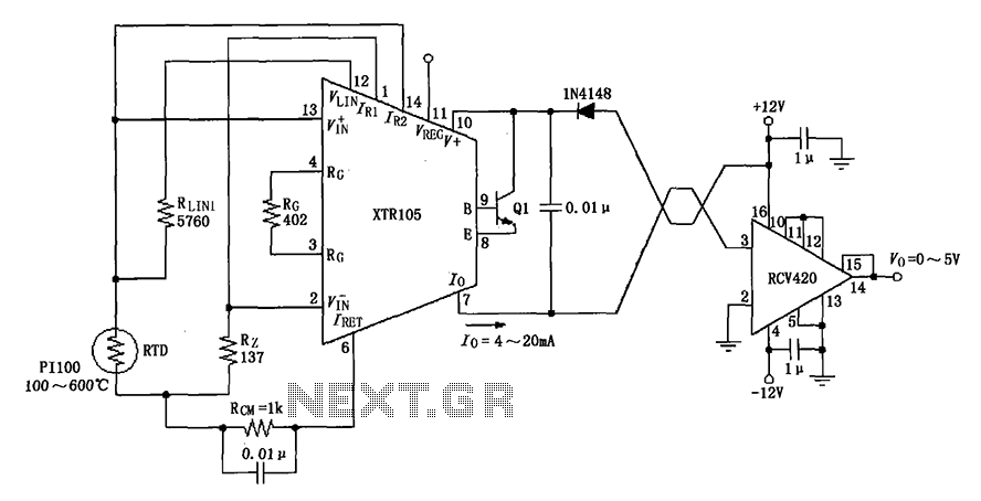
The circuit utilizes a Pt100 type resistance temperature detector (RTD). It operates within a temperature range of 100 to 600 °C, where the XTR105 outputs a current of 4 to 20 mA, and the RCV420 provides an output voltage...
This simple variable power supply circuit has a low production cost and delivers an output voltage between 1.5 V and 15 V with a maximum current of 500 mA. This variable power supply circuit is designed to provide a versatile...
This audio power amplifier is highly suitable for portable devices or as a headphone amplifier. The circuit design of this audio power amplifier is straightforward. This audio power amplifier circuit is designed to enhance audio signals for portable devices and...
The project involves displaying the current room temperature using an LM35 temperature sensor. This schematic differs from a previous schematic that utilized a multiplexed seven-segment display. In the earlier schematic, the display select I/O pins were RA0, RA1, RA2,...