
Lamp flasher using LM317

The lamp flasher circuit is designed to provide a visual signaling mechanism, commonly used in automotive lighting systems for indicators or decorative lighting. The LM317T voltage regulator is a versatile component known for its ability to maintain a steady output voltage despite variations in input voltage or load conditions. In this application, it is configured to control the flashing of the lamp.
The circuit operates by charging and discharging capacitors C2, C3, and C4 through the resistors R1, R2, and R3. The resistors and capacitors form an RC timing circuit, where the values selected dictate the charging and discharging times, thus determining the flash rate. The use of multiple resistors and capacitors allows for fine-tuning of the desired flashing frequency.
For implementation, the circuit can be powered by a standard automotive voltage supply (typically 12V). The output from the LM317T can be connected to the lamp, which will flash according to the established timing parameters. Safety measures should be taken to ensure that the circuit components are rated appropriately for the automotive environment, where vibrations and temperature fluctuations may occur.
In summary, this lamp flasher circuit using the LM317T voltage regulator is an effective solution for creating visual signals in automotive applications. The design's flexibility in adjusting the flash rate through resistor and capacitor selection makes it a valuable tool for engineers and hobbyists alike.Here is a very useful lamp flasher circuit using the famous adjustable voltage regulator IC LM317T. LM317 can source up to 1A of current and so up to 12W lamps can be used with this flasher. Such a circuit finds huge application in automobiles. The frequency of the flashing depends on the value of resistors R1 to R3 and capacitors C2 to C4. With th e given values; the flashing rate is around 5 flashes per second. 🔗 External reference
Related Circuits

This is a three-mode lamp dimmer circuit with touch control. This circuit can be used to control a lamp in three operation modes: dim, off, and bright. A NE555 timer is utilized in the design. The three-mode lamp dimmer circuit...
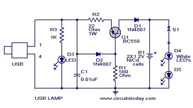
A simple USB LED lamp circuit utilizing a 5-volt power supply sourced from a USB port, designed to illuminate a desktop or laptop computer during power outages. The USB LED lamp circuit operates by converting the 5-volt DC power provided...

The DW15-200-630A breaker solenoid is a DC solenoid designed for short-time operation. The DK-1 control box utilizes an AC power switch to manage the electromagnet circuit, as depicted in Figure 6-7. The DK-1 type electromagnetic control box includes several...
To make an LED function, a voltage source is required that exceeds the LED's forward bias voltage, which is typically greater than 1.5V (approximately 2V for red LEDs). To effectively operate an LED, it is essential to provide a voltage...
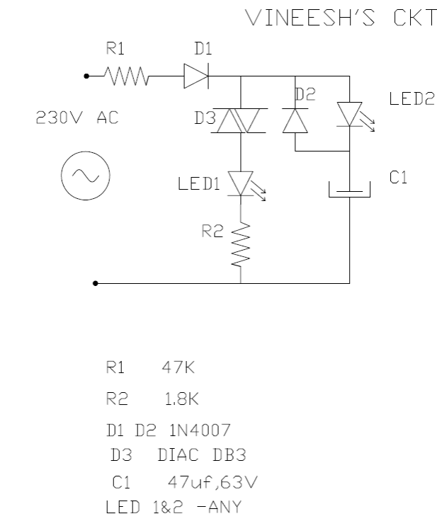
The following mains-operated LED flasher circuit, which is essentially an astable multivibrator circuit, utilizes a diac and resistor arrangement to achieve an interesting wig-wag flashing effect with two LEDs. The circuit was shared by Mr. Vineesh, a dedicated follower...
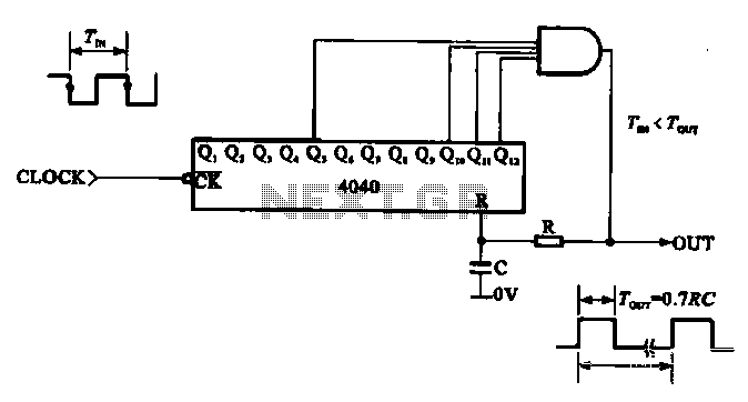
This document illustrates the application of a CMOS integrated circuit (IC) count divider, specifically the TC4040, which functions as a 12- or 14-bit counter. The circuit can be configured to achieve various frequency division ratios, such as a 1:3600...