
laser communication
The project entails the design and implementation of a laser-based communication system that transmits audio signals in a digital format. The primary components of this system include the MP3 player, PCM encoder/decoder chips, a laser transmitter, and a laser receiver. The PCM encoder converts the analog audio signals from the MP3 player into digital pulses, which are then transmitted via the modulated laser beam. The DPLL plays a crucial role in maintaining synchronization between the transmitter and receiver, ensuring that both systems operate in harmony, particularly in timing the clock signals necessary for accurate data transmission.
The laser transmitter modulates the laser beam based on the digital output from the PCM encoder. The modulation scheme represents binary data, where the presence of light indicates a binary 1 and the absence indicates a binary 0. The laser receiver, positioned to capture the transmitted beam, demodulates the incoming signal back into digital data. This data is then fed into the PCM decoder, which converts it back into an analog signal for output.
The design must also account for environmental factors that may affect the laser signal, such as atmospheric conditions and obstacles. To enhance the system's performance, a parabolic reflector may be integrated into the design to focus the laser beam, thereby increasing the effective transmission distance. The overall system architecture must ensure that the integrity of the signal is maintained throughout the transmission process, providing a reliable means of communication.
In summary, this project successfully integrates various electronic components and principles to create a functional laser communication system capable of transmitting audio signals digitally, showcasing advancements in communication technology and the potential for innovative applications in the field.The aim of this project is to transmit analog sound from a commercial mp3 player digitally using a store-bought laser pointer as the transmitter. This will be achieved mainly by performing analog-digital conversions, and by using a digitally phase-locked loop (DPLL) to synchronize the clock signals on both the transmitter and the receiver.
This pr oject was carried out in Jan 2012 - April 2012 as a group of 5 team-mates. Since the beginning of civilization, man has sought to communicate with each other over long distances. From the primitive usage of smoke signals to groundbreaking technologies of their time such as the telegraph and telephone, communication technology has seen rapid improvement and development in recent years into today`s 3G/4G cellular data networks and fiber-optic internet linkage which are commonly used by people worldwide.
The ability to convert analog signals to digital ones for transmission has revolutionized the communication industry. Out of the various types of analog-digital transmissions, the Pulse Code Modulation (PCM) scheme is one of the most common.
Apart from its usage in audio recording and compression, the PCM scheme is also used in Public Switch-Telephone Networks (PSTNs), whose primary objective is to use a modulation scheme to convert analog human voice signals into digital signals for transmission, and also to be able to convert the digital signals back into the original analog signal after reception. In comparison with analog transmissions, digital data transmissions have the significant advantage that discrete and finite levels of digital signals have intervals which cause it to be less vulnerable to distortions caused by ambient noise, which in turn make recovering the signal much easier.
One way of transmitting digital data wirelessly is by using a laser beam. As digital signals are purely made up of ones and zeroes, we can take the laser beam being on` as sending a 1`, and take the laser beam being off` as sending a 0`. Also, using laser communication systems increases cost effectiveness when compared to the conventional method of copper wire.
A basic laser communication system can transmit data a few hundred meters. Throw in a parabolic light reflector and it may achieve a transmission distance of a few kilometers. Furthermore, the laser link is highly secure as it is virtually impossible for an external party to tap into the link, as any interception will cause a break in data flow, alerting the user immediately. From this discussion, the benefits of a laser communication system can be clearly seen. Before beginning the project, our group first considered the basic building blocks of an analog-digital data transmitter.
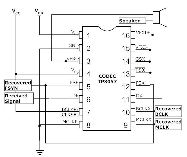
We had all performed this task before in our weekly 3 hour pair-work lab sessions earlier this semester before we started on this project. Figure 1 shows a simple example of how 2 PCM encoder/decoder chips are connected to take in and output an analog signal while transmitting it digitally.
Circled in Green is the connection through which the actual data is being transmitted. Circled in Red are the 3 clocking signals, generated externally, essential for both chips to work in tandem. The 3 clocking signals are namely the Master Clock (MCLK), Bit Clock (BCLK) and the Frame Synchronization (FSYN).
One might then question why it takes a group of five people two months to achieve something which we have already achieved in pairs and took us no more than 3 hours. The reason is simple, for us to convert the schematic in Figure 1 into a wireless communication system, we have to remove any and all wired connections between both chips.
For visualization purposes, imagine Figure 1 being cut in half vertically down its center. It is not just a matter of replacing the data connection (circled in green) with a laser transmitter/receiver circuit. More importantly, we have to retrieve 3 clock signals (circled in red). T 🔗 External reference
Related Circuits
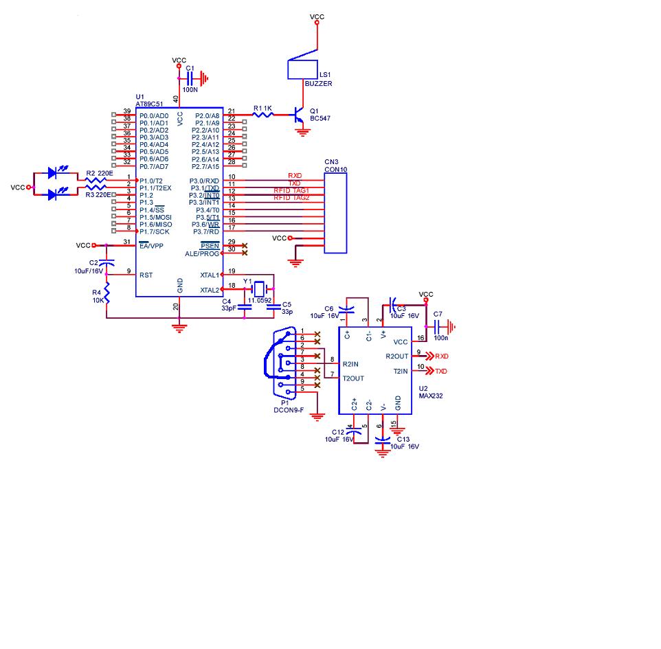
A project is being developed utilizing RFID (Radio Frequency Identification) technology. The microcontroller chosen for this project is the AT89C51/52/S52. Serial communication is being implemented using RS-232. The project involves the integration of RFID technology for identification and data exchange...
This train detector makes use of hand held laser pointer devices that are widely available to detect trains over long distances. The described train detector system utilizes handheld laser pointer devices as a primary component for the detection of trains...
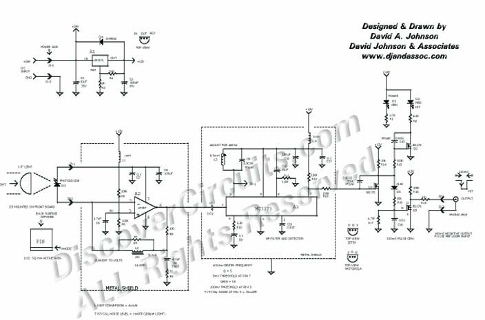
This circuit was originally designed to detect weak flashes of laser light reflected off a fabric video projection screen. It was used as part of a firearm training system. It generates a 100 ms output pulse whenever it detects...
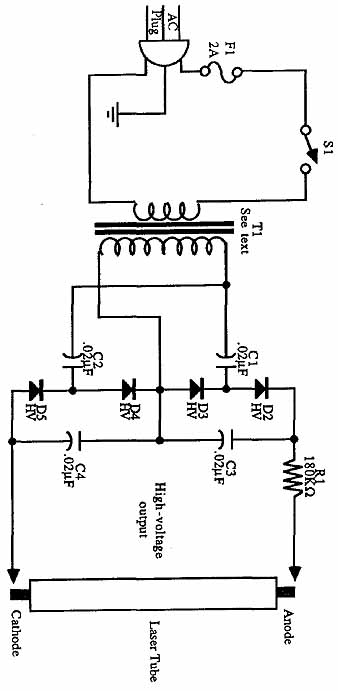
Construct universal power supplies, including low-voltage power supplies for operating electronic equipment. The designs include single- and dual-voltage regulated supplies, an all-purpose adjustable version, and battery pack regulators. A helium-neon laser tube requires a high-voltage power supply for operation....
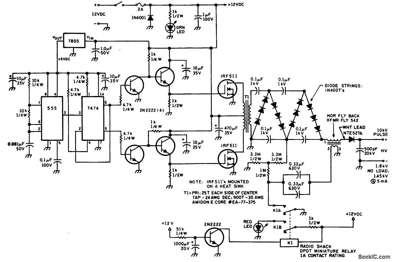
The helium-neon laser requires two voltages: one in the range of 10 kV to initiate the laser, which is turned off once the discharge begins, and a lower-voltage power supply to sustain the discharge. The circuit diagram illustrates a...
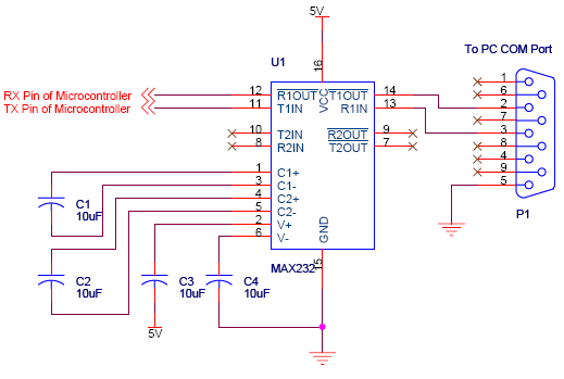
Serial communication using UART or USART of a microcontroller 8051 AVR PIC, software implementation of half-duplex UART and MAX232 interfacing with microcontrollers 8051 AVR PIC. The described system focuses on implementing serial communication via UART (Universal Asynchronous Receiver-Transmitter) or USART...