
HELIUM NEON LASER PS WITH HV PULSE IGNITION

The helium-neon laser circuit is designed to operate with two distinct voltage levels essential for its functionality. The initial high voltage, approximately 10 kV, is crucial for initiating the laser process. This high voltage is momentarily applied to ionize the gas mixture within the laser tube, allowing for the production of coherent light. Following the initial discharge, the high voltage is removed, and a lower voltage is maintained to sustain the laser's operation.
The circuit employs a capacitor charged by a fraction of the main supply voltage. This capacitor acts as an energy storage element, which is then discharged through a high-voltage ignition transformer. The ignition transformer elevates the voltage to the required level for the initial gas ionization. The design incorporates a delay circuit that ensures the main power supply reaches its full operational voltage before the capacitor is discharged. This delay is critical to prevent premature ignition and ensure stability in the system.
A non-latching relay is utilized to control the discharge of the capacitor into the ignition coil. This relay operates on a one-shot basis, meaning it will only activate once per trigger event, allowing for precise control over the timing of the ignition pulse. The high-voltage diode placed in series with the ignition coil serves to rectify the output from the ignition transformer, converting the damped oscillatory waveform into a single positive pulse. This pulse is then directed to the laser tube, effectively ionizing the gas and initiating the laser action.
Once the gas within the laser tube is ionized, the main power supply takes over to maintain the discharge, ensuring continuous operation of the laser. The overall design of this circuit is vital for achieving reliable and efficient laser performance, highlighting the importance of precise voltage control and timing in high-voltage applications.The helium-neon laser requires two voltages: a voltage in the range of 10 kV that starts the laser and then turns off once the discharge begins, and a lower-voltage power supply to sustain the dis-charge. The circuit diagram illustrates one method of generating the laser ignition voltage. A fraction of the main supply voltage is used to charge up a capacitor. When triggered, it is discharged through a high-voltage ignition transformer in series with the main power supply output. When the supply is first turned on, a delay circuit allows the main supply to stabilize at full voltage and charge up the capacitor.
A nonlatching relay operates to discharge the capacitor into the ignition coil on a one-shot basis after the timing delay. The HV diode in series with the ignition coil and the capacitor across the supply rectifies the damped oscillatory waveform out of the ignition coil, producing a single positive pulse across the laser tube to ionize the gas in the laser.
Once the laser is ignited by the HV pulse, the main power supply maintains the discharge. 🔗 External reference
Related Circuits
A pulse generator typically allows control over the pulse repetition rate, pulse width, pulse delay, and pulse amplitude. More advanced pulse generators may also enable adjustments to the rise time and fall time of the pulses. The delay of...

This circuit powers a 6-inch, 4-watt fluorescent tube using a 12-volt supply, with a current consumption of 300 mA. The circuit designed for powering a 6-inch, 4-watt fluorescent tube from a 12-volt supply consists of several key components to ensure...
Here's a circuit to create a buzzcoil using a standard automotive ignition coil. A 556 dual timer is used to establish the frequency and duty cycle of the coil current. One of the timers is used as an oscillator...
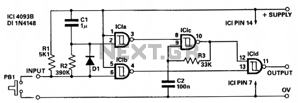
The circuit provides independent control of the initial delay and pulse rate. ICIc functions as a pulse generator, with its operation inhibited by the normally low output of ICla. When the circuit input transitions to low (e.g., when pressing...
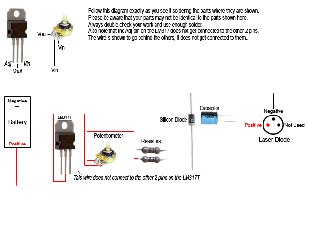
Construct a custom burning laser. This guide outlines a proper method for building a burning laser, ensuring a long lifespan for the device. There are multiple advantages to this approach over simply connecting the laser diode to batteries, which...
The first example utilizes a standard op-amp oscillator circuit to produce a triangular waveform, which is then level-shifted and supplied to a comparator (e.g., LM339) to generate a PWM waveform. It is common for users to prefer using two...