
Latch Switch

This circuit utilizes a non-locking push switch (S1) to control the activation of a load, which can be represented by various components such as a resistor (R5) and a diode (D1), or potentially a lamp or relay. The circuit is designed such that the load remains activated until the power supply is interrupted. An optional switch (S2) can be included to break the power supply to the circuit, allowing for a reset mechanism. If S2 is excluded, the only method to reset the circuit would involve disconnecting the power source, such as unplugging a battery or disconnecting from an electrical outlet.
Upon initial power application, or when S2 is toggled, the capacitor (C1) begins to charge through the base-emitter junction of the transistor (Q1). This charging process generates a brief positive pulse at the base of Q1, which causes Q1 to enter saturation. In the saturated state, the collector-emitter voltage of Q1 approaches zero volts, effectively allowing current to flow through the load. With Q1 in this state, the second transistor (Q2) remains off, preventing any unwanted activation of additional components in the circuit.
The design of this circuit is particularly useful in applications where a momentary switch is desired to control a load that remains on until power is removed. The inclusion of C1 allows for a smooth transition during the activation phase, ensuring that the load is turned on reliably. The optional switch S2 provides flexibility for the user, enabling a straightforward method to reset the circuit without needing to physically disconnect the power supply. Overall, this circuit offers a simple yet effective solution for controlling various loads in electronic applications.In this circuit a non-locking push switch is used to activate a load. The load remains switched on until power is removed from the circuit. The load is represented by R5 and D1, but could be a lamp, a relay or another circuit. S2 breaks power to the circuit but could be omitted altogether. If S2 is left out, then reset would be by disconnecting the power; this would mean unplugging the battery if battery powered or disconnecting from the electrical outlet. When first plugged in (or S2 is operated) C1 charges via the base emitter junction of Q1 and hence a brief positive pulse is applied. Q1 will switch on and be saturated, its collector emitter voltage being close to zero volts. Q2 is therefore off, and the 🔗 External reference
Related Circuits
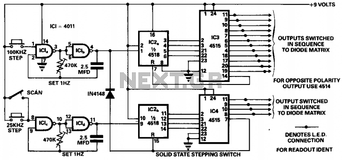
This circuit was designed to ensure safe operation of a 48-channel mobile transceiver while in motion. It incorporates oscillators that facilitate single-stepping or scanning functions. The scanning feature enables the user to sequentially check all 48 channels for occupancy,...
National Semiconductor has been designing and manufacturing integrated circuits (ICs) for switch-mode power supplies for many years. The application of these devices is typically straightforward, supported by comprehensive documentation. A common example of a switch-mode power supply is based...
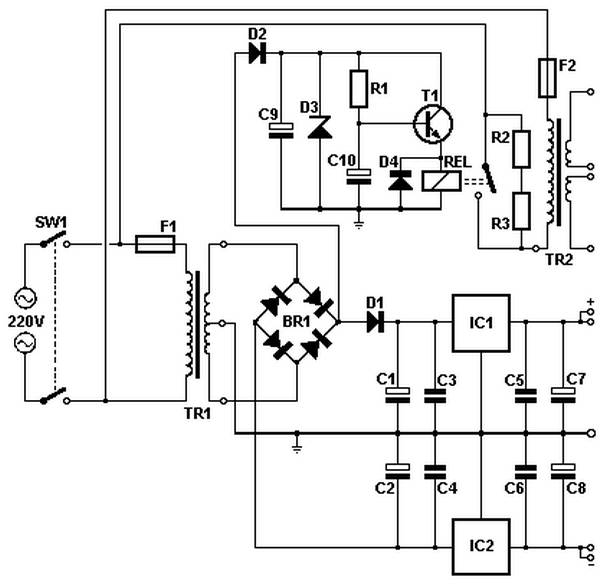
Soft power for a large transformer is implemented by using a series resistance of 100 ohms at 10 watts, or alternatively, two resistors of 47 ohms at 5 watts each in the primary circuit. The resistance is bypassed by...
The following touch switch circuit utilizes a CA3240 dual BiMOS operational amplifier to detect small currents flowing between the contact points on a touch plate. The touch switch circuit employs a CA3240 dual BiMOS op-amp, which is known for...
A circuit that will find enough applications. Basically, the designing became in order to exist delay in quench one or more lamps in a stairwell or in any other space exists this need. It can become use for the...
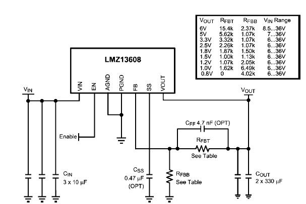
A simple, high-efficiency switching power supply circuit can be designed using the LMZ13608 8A regulator. This regulator offers very high efficiency and requires few external components. It supports a wide input voltage range of 6 to 36 volts and...