
Direct Coupled On/Off Touch Switch

The touch switch circuit employs a CA3240 dual BiMOS op-amp, which is known for its high input impedance and low offset voltage, making it ideal for sensing minute variations in current. The circuit operates by applying a small voltage to the touch plate, which is connected to one of the op-amp's inputs. When a finger touches the plate, it changes the capacitance and induces a small current that the op-amp can detect.
The configuration typically includes resistors and capacitors to set the sensitivity of the touch detection, allowing the circuit to respond to light touches while ignoring noise or unintentional contact. The output of the op-amp can be connected to a microcontroller or a transistor to control a load, such as an LED or a relay, based on the detected touch.
To enhance reliability, the circuit may incorporate hysteresis to prevent false triggering from noise or minor fluctuations in the signal. Additional features might include adjustable sensitivity through variable resistors, enabling the user to calibrate the touch response according to specific requirements.
Overall, this touch switch circuit design provides an efficient and effective method for implementing touch-sensitive controls in various applications, ranging from consumer electronics to industrial automation systems.The following touch switch circuit uses a CA3240 dual BiMOS op amp to sense small currents flowing between the contact points on a touch plate. Since this.. 🔗 External reference
Related Circuits
The circuit below is designed to be used with the bi-directional lamp sequencer shown above on this same page. Two additional transistors are used to increase the current from the 74HCT138 decoder to control 12 volt 25 watt lamps....
In this small switching power supply, a Schmitt trigger oscillator is used to drive a switching transistor that supplies current to a small inductor. Energy is stored in the inductor while the transistor is on, and released into the...
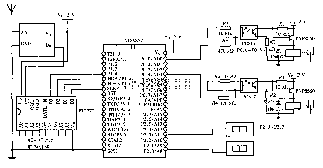
This design aims to create a long-distance wireless remote control switch lighting control system, which consists of a transmission system and a reception system. The system utilizes wireless transceiver modules for RF transmission and reception. The transmitting portion mainly...
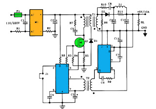
The schematic above illustrates a 10A power supply with a 5V output and a power rating of 50W. It operates as a flyback converter in continuous mode. The circuit includes both primary and secondary side controllers, providing comprehensive protection...
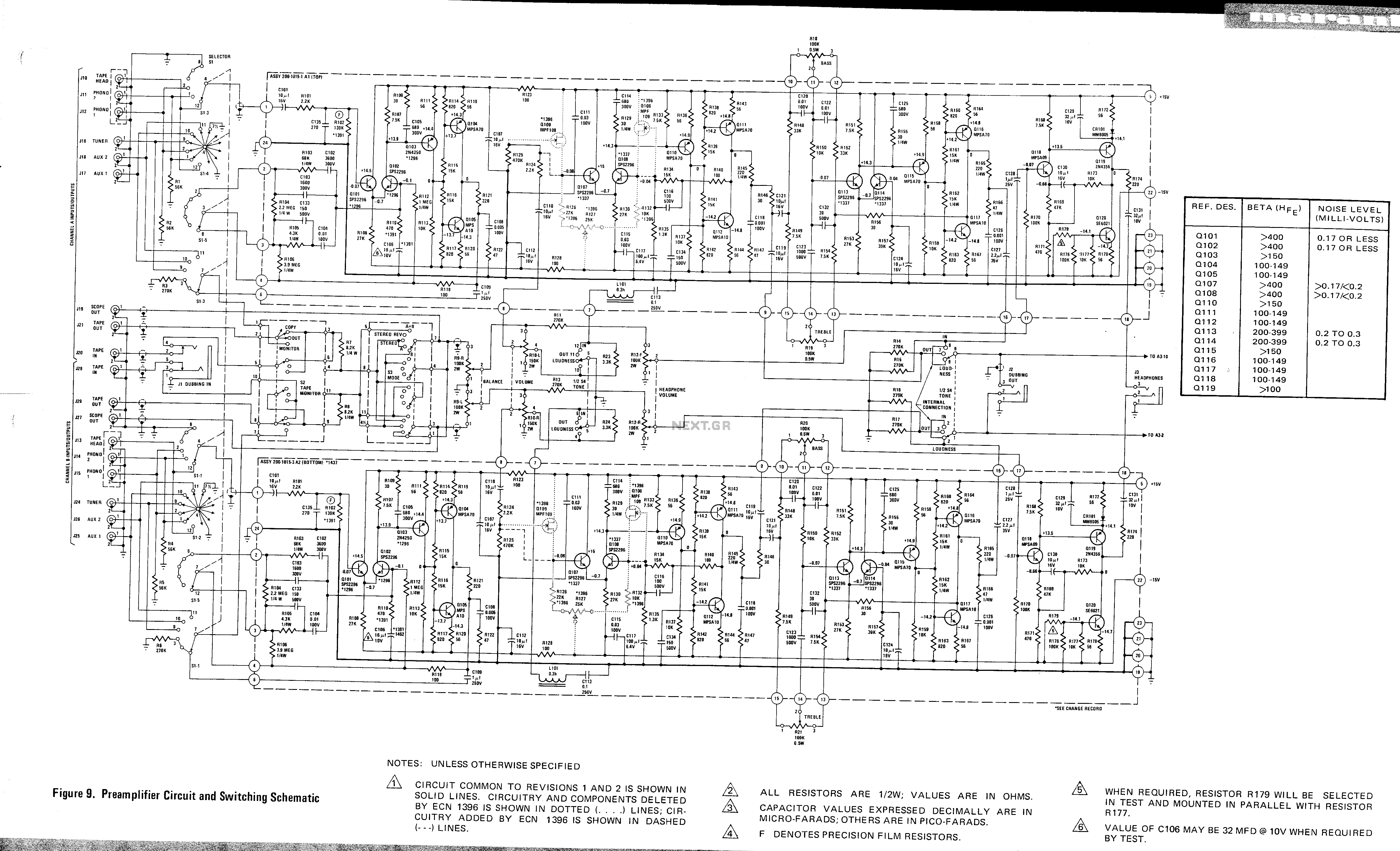
This is a preamplifier circuit and switching schematic for the Marantz Model 33. The Marantz Model 33 preamplifier circuit is designed to amplify low-level audio signals from various sources before sending them to a power amplifier. The schematic typically includes...
.png)
The one-touch turn signal (OTTS) module enhances the functionality of the turn signal lever by adding a mode where a single touch makes the indicators blink for a certain number of times. This behavior is also known as lane...