
LCD 7 digit HF counter
The circuit described involves a transistor configuration where a resistor, typically valued at around 47k ohms, is placed between the base and collector terminals of a transistor. This resistor serves a critical role in determining the operating point of the transistor, allowing for adjustments based on the specific characteristics of the transistor used in the application.
In this configuration, the transistor operates in a common-emitter mode, where the base-emitter junction is forward-biased, and the collector-emitter junction is reverse-biased. The choice of resistor value is essential, as it influences the base current and, consequently, the collector current. A higher resistance value may result in reduced base current, which can lead to lower collector current, while a lower resistance value increases the base current, allowing for greater amplification.
The mention of a PIC (Peripheral Interface Controller) indicates that this circuit may be part of a larger system where the PIC controls the transistor's operation. In the absence of the PIC, it is specified that the voltage at the collector should be maintained at 2.5 V. This suggests that the circuit is designed to operate at a specific voltage level, which could be critical for interfacing with other components or for ensuring proper operation within the intended application.
The design allows for flexibility in tuning the circuit by changing the resistor value to match the characteristics of different transistors, which may have varying current gain (beta) values and threshold voltages. This adaptability is crucial in applications requiring precise control over signal amplification or switching functions. Overall, the configuration aims to achieve reliable performance while accommodating variations in transistor specifications.The resistor between basis and collector (around 47k) is to be individually set according transistor characteristics. Without PIC in socket at the collector should be 2.5 V. 🔗 External reference
Related Circuits
This circuit allows the use of the keys "1, 2, 3, 4" on a Philips TV IR remote to control three relays. The key "4" specifically activates the over-temperature alarm. The LM35 temperature sensor can detect temperatures from 0°C...
This is a digital dice circuit that uses the PIC16C84. The digital dice circuit utilizing the PIC16C84 microcontroller is designed to simulate the random rolling of a standard six-sided die. The circuit operates by generating a random number between 1...
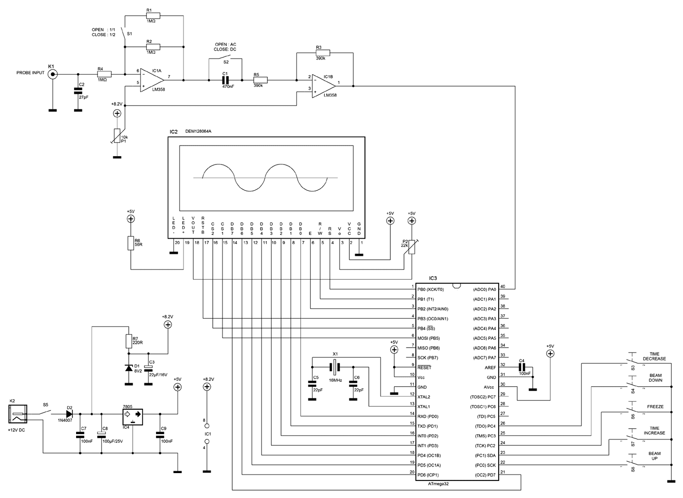
A few months ago as I was surfing on the net, I saw an oscilloscope based on PIC18F2550 microcontroller and a KS0108 controller based graphical LCD. That was Steven Cholewiak's web site. I had never seen before so amazing...
This document will present an overview of two critical components within a one-chip computer: the timing/counter system and the interrupt system. Through this explanation, readers will gain insight into the operating principles of these systems. For illustration, consider an...
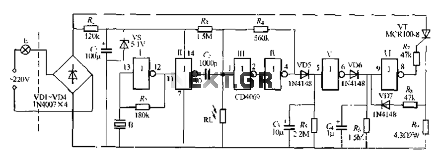
The circuit is designed for sound and light control of stairway and walkway lighting. It features high immunity and includes soft-start and over-current protection mechanisms. During the day, the photosensitive resistor has low resistance, resulting in a low voltage...
The DD-2 is a highly regarded digital delay pedal that emulates an analog sound. It was initially sold from 1983 until it was discontinued in 1986, after which it was relaunched without any modifications as the DD-3 (noting that...