
AVR LCD Microcontrolled Oscilloscope

The operating voltage of the circuit is 12V DC. By this voltage, the power supply is producing 2 voltages: +8.2V for IC1 and +5V for IC2 and IC3. This circuit can measure from +2.5V to -2.5V or from 0 to +5V dependent by S1 position (AC or DC input). By using a probe with 1:10 division, it is possible to measure almost 10 times higher voltages. Moreover, with S2, an extra division by 2 of the input voltage can be achieved.
Programming the ATmega32 involves burning the ATmega32 with the AVR_oscilloscope.hex file and selecting an external crystal in the fuses section. It is crucial to disable the JTAG interface from the ATmega32 microcontroller; otherwise, the device will restart at the initial screen when transitioning to the oscilloscope screen.
Calibration of the oscilloscope requires adjustment of two components: the LCD contrast trimmer (P2) and the beam positioning potentiometer (P1). To calibrate, apply power to the circuit, then adjust P2 until the pixels on the screen are clearly visible. Following this, adjust P1 to center the beam on the LCD along the horizontal line of the cross.
Usage of the oscilloscope involves controlling the beam's vertical position using buttons S8 (up) and S4 (down) to measure voltage, with 1 volt corresponding to 1 square height on the display. The measurement speed can be adjusted using S7 (increase speed) and S3 (decrease speed), with a minimum displayable waveform frequency of 460Hz. For lower frequency waveforms, such as 30Hz, the S7 button can be pressed to shrink the waveform or S3 to extend it up to the maximum sampling rate. The oscilloscope features an automatic trigger function, which is effective for continuous signals (e.g., triangle waveforms). For unstable signals (e.g., serial transmission), the screen can be frozen by pressing S6, allowing for a snapshot of the measurement signal, which will end upon releasing the S6 button.A few months ago as I was surfing on the net, I saw an oscilloscope based on PIC18F2550 microcontroller and a KS0108 controller based graphical LCD. That was Steven Cholewiak's web site. I had never seen before so amazing microcontroller-only oscilloscope. That was realy impressive circuit, so I decided to design something like that but in C language instead of assembly that I was using all those years.
The best solution for me was the WinAVR as it bases on open source AVR-GNU compiler and it works perfect with AVR studio 4. The graphics library that I used, is made by me specific for this project. It's not for general use. If you want to include it to your codes, you have to convet it as you need to. The maximum signal speed who can show up this oscilloscope is 5 kHz in square signal. For other signals (sine or triangle) the frequency is lower ( almost 1 kHz) for having clear view of the signal. Description The operating voltage of the circuit is 12V DC. By this voltage, the power supply is producing 2 voltages. +8.2V for IC1 and +5V for IC2 and IC3. This circuit can measure from +2.5V to -2.5V or from 0 to +5V dependent by S1 position (AC or DC input).
By using probe with 1:10 division you can measure almost 10 times higher voltages. Moreover, with S2 you can make an extra division by 2 the input voltage. Programming The ATmega32 Burn the ATmega32 with AVR_oscilloscope.hex and select external crystal at the fuses section. After that, you Must disable the JTAG interface from your ATmega32 microController. If you don't do that, the mega32 will show you the initial screen and when it go to the oscilloscope screen it will restart immediately to the initial screen and it will stay there for ever.
Calibrations The only 2 things you have to calibrate is the LCD contrast trimmer P2 and the P1, to move the beam at the center of the LCD. To do that, apply only the power supply to the circuit and adjust the P2 up to the point you will see clear the appeared pixels on the screen.
Then, adjust the P1 up to the point the beam is moved at the middle of the LCD (at the horizontal line of the cross). Usage You can move the beam up or down the screen by pressing the buttons S8 or S4 correspondingly to measure the voltage of the signal.
1 volt is taking up 1 square height. With S7 and S3 you can increase or decrease the measurement speed. The minimum speed of a waveform that can be displayed on LCD is 460Hz. If you want to view a lower frequency waveform, for example 30 Hz, you can press the S7 to shrink the waveform or S3 to extend the waveform up to the maximum sampling rate. This oscilloscope has an automatic trigger. That means, if you have a continuous signal (ex a triagle waveform) the auto trigger will work perfect.
If your signal is not stable (ex a serial transmittion) you can freeze the screen by pressing S6 switch. At his case you can get a snapshoot of your measurment signal. By the time you release the S6, the snapshoot will end. 🔗 External reference
Related Circuits
The Atmel AVR series are very good microcontrollers with quite a rich instruction set, rich enough that lots of folks have good compilers for them so we don’t have to learn their assembler. A very rich compiler available is...
This adaptor lets me program 8 or 20 pin DIP devices using the In-System Programmer (ISP) described in Atmel's AVR910 application note. This circuit provides power and clocks for the part to be programmed and power to the ISP...
This instrument requires two precision components: A precision capacitor and a precision inductor. You only need to start with one precision component, either the reference capacitor or the reference inductor, and using this meter, you can select or adjust...
A segment can be tested by applying an alternating voltage of a few volts across it. It is important to note that applying a direct voltage can cause irreversible damage to the display, as the resulting current will remove...
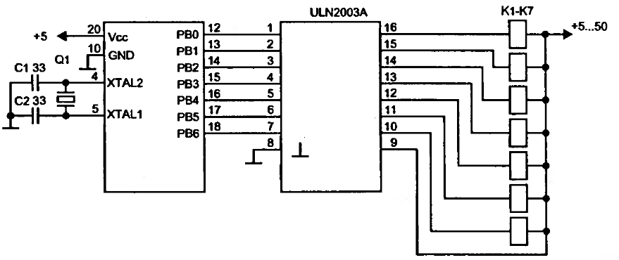
To drive a relay, a current greater than 20mA is required, which cannot be supplied by a single microcontroller pin. Therefore, a relay cannot be connected directly to a microcontroller pin. Instead, a simple amplifier circuit consisting of a...
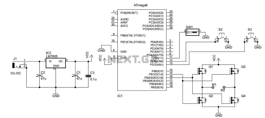
A DC motor from an old personal stereo cassette player has been utilized in this circuit, which provides control over both the speed and direction of the motor. The circuit employs PWM waveforms to drive a MOSFET H-bridge, as...