
LCD Interfacing with AVR-Atmega8 and Atmega32

The interfacing of an LCD display with AVR microcontrollers, such as the Atmega8 and Atmega32, is a common task in embedded systems design. This process typically involves connecting the LCD to the microcontroller's GPIO (General Purpose Input/Output) pins, configuring the pins for data and control signals, and writing a program in embedded C to control the display.
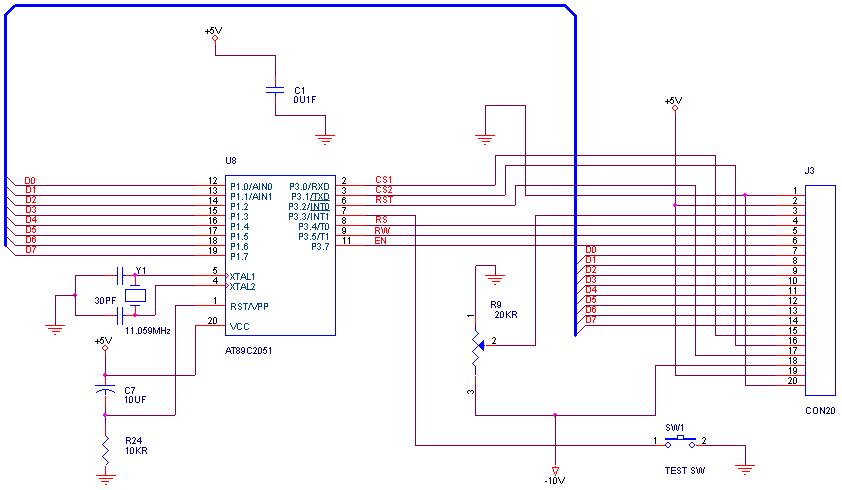
The circuit diagram for this setup generally includes the following components:
1. **LCD Display**: A standard 16x2 character LCD is commonly used. It has 16 pins, including 8 data pins (D0 to D7), 3 control pins (RS, RW, E), and power supply pins (VSS, VDD, VO).
2. **Microcontroller**: The Atmega8 or Atmega32 microcontroller, which serves as the brain of the operation, controlling the LCD based on the programmed instructions.
3. **Resistors and Potentiometer**: A potentiometer is often used to adjust the contrast of the LCD. Additionally, pull-up or pull-down resistors may be used for stability in certain configurations.
4. **Power Supply**: The circuit requires a stable power supply, typically 5V, to ensure proper operation of both the microcontroller and the LCD.
In terms of programming, the embedded C code will typically include functions to initialize the LCD, send commands, and display characters or strings. The initialization sequence is crucial for setting up the LCD in the desired mode (4-bit or 8-bit), and it usually involves sending specific commands to configure the display settings.
The structure of the code will include:
- Header files for AVR libraries.
- Definitions for control and data pins.
- Functions for initialization, sending commands, and writing data to the display.
- A main function that initializes the LCD and demonstrates its functionality by displaying text.
This comprehensive approach ensures a successful interface between the LCD and the AVR microcontrollers, allowing for effective data presentation in various embedded applications.Interfacing LCD Display to Avr micro controllers-Atmega8 and Atmega32 with circuit diagram and code/program using embedded C to download.. 🔗 External reference
Related Circuits
How can graphical LCDs be controlled using a microcontroller? Is there any datasheet available? Graphical LCDs (Liquid Crystal Displays) are widely used in various electronic applications for displaying complex graphics and text. To control these displays with a microcontroller, several...
Analog to Digital Converter (ADC) interfacing with microcontrollers such as AVR, 8051, and PIC, including Digital-Ramp ADC, Successive Approximation ADC, Flash ADC, and basic working of an analog to digital converter. Analog to Digital Converters (ADCs) are essential components in...
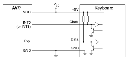
In many situations, a human interface is required for microcontroller projects. This example describes the interfacing of an AVR microcontroller with a standard PC AT keyboard. According to the keyboard timing diagram, the keyboard transfers data to the host...
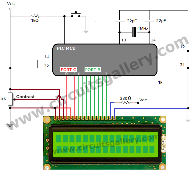
The process of interfacing an LCD (Liquid Crystal Display) module with a PIC microcontroller involves understanding the nature of LCDs as passive components that modify light rather than generate it. LCDs are specifically designed for use with microcontrollers and...
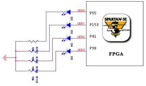
The Spartan-3E board features four LEDs connected to FPGA I/O pins, as detailed in the accompanying table. Each LED's cathode is connected to ground through a 330-ohm resistor. To illuminate a specific LED, the corresponding FPGA control signal must...
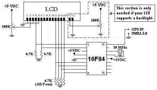
This is a project that I started back late 2003 when I just starting to learn PIC programming. I wanted to building something that actually did something useful. This project is based on a PIC16F84. I actually came up...