
LCD Module Control with PC

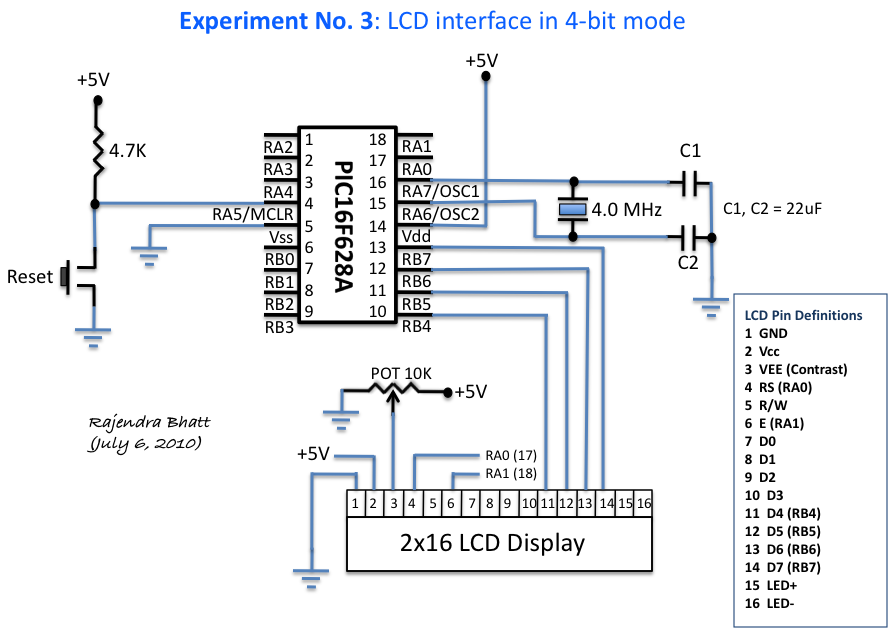
The circuit described is designed to interface a 2-line by 16-character Liquid Crystal Display (LCD) with a personal computer through a parallel printer port. The parallel port serves as a communication interface, allowing data and control signals to be sent from the PC to the LCD module. The circuit does not utilize the bi-directional capabilities of modern printer ports, making it compatible with a wide range of older parallel ports.
The LCD module operates using a set of control signals, specifically the Enable (E) and Register Select (RS) pins, which are essential for its operation. In this configuration, the Enable pin is responsible for signaling the LCD when to read the data present on the data pins, while the Register Select pin determines whether the data being sent is command data or character data. Both of these pins are connected to the Control Port of the parallel interface.
The Control Port is configured as an open collector or open drain output. This configuration allows multiple devices to be connected to the same line without risk of contention, as the output can only pull the line low, and an external pull-up resistor is required to pull the line high when not driven low. While many parallel ports include internal pull-up resistors, some do not, which necessitates the incorporation of external pull-up resistors in the circuit to ensure proper operation.
The data pins of the LCD are typically connected to the data lines of the parallel port, allowing for the transmission of character data. The circuit may also include additional components such as resistors and capacitors to stabilize the power supply and filter noise, ensuring reliable operation of the LCD module.
Overall, this circuit is a practical solution for displaying text from a PC on a standard LCD module, leveraging the simplicity and accessibility of the parallel printer port interface. The design is particularly useful for applications where a low-cost and straightforward display solution is required.This simple circuit controls a popular 2-line x 16-character LCD by a PC via printer port. It doesn't use the Bi-directional feature found on newer printer ports, thus it should work with most, if no all Parallel Ports. These LCD Modules are very common these days, and are quite simple to work with, as all the logic required to run them is on board.
The LCD panel's Enable and Register Select is connected to the Control Port. The Control Port is an open collector / open drain output. While most Parallel Ports have internal pull-up resistors, there are a few which don't. Therefore by incorporating the 🔗 External reference
Related Circuits
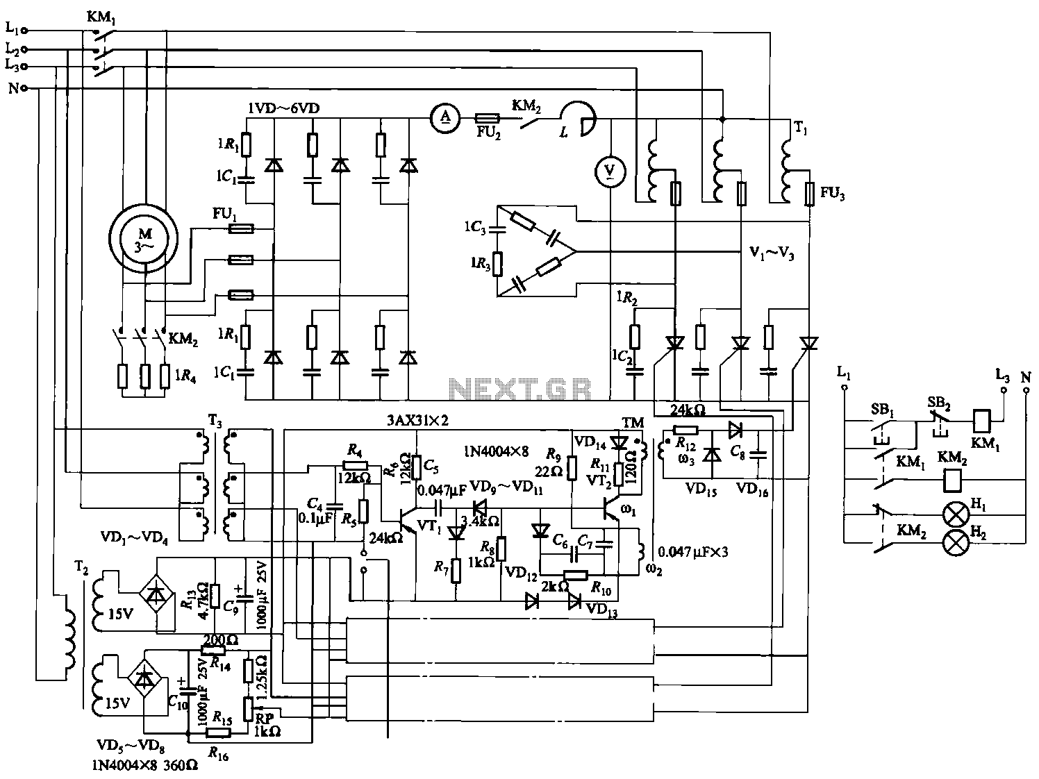
The circuit depicted in Figure 3-170 illustrates a wound rotor induction motor operating at various speeds, with a voltage (turn difference frequency EMF) U induced in the rotor. The rotor open circuit voltage is represented as Uo (Us0). A...
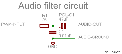
The signal from the MSP430 PWM pin is not suitable for directly driving a speaker or amplifier. To improve the signal quality, it is advisable to process it through a low-pass filter, which smooths out the sharp edges of...
An HD44780 Character LCD is a liquid crystal display (LCD) device designed for interfacing with embedded systems. These screens are available in various configurations, including 8x1 (one row of eight characters), 16x2, and 20x4. The most commonly produced configuration...
A circuit is being designed to drive a 4x7 segment display using a PIC microcontroller. The previous implementation utilized four pins to control each of the four digits individually, with a sequential activation method. The designer aims to simplify...
The circuit features a delay action with an instantaneous reset control mechanism. It is categorized into three types: a conducting pipe rechargeable delay circuit, a tube cut-off control rechargeable delay circuit, and a discharge-type delay circuit. In the conducting...
This integrated circuit is highly efficient and does not require any external glue logic for operation. It features two pins for motor control: one pin is dedicated to controlling the direction of the motor, while the other pin is...