
Conducting pipe control rechargeable delay circuit

The described delay action circuit operates by utilizing transistors as switches to control the flow of current based on the input voltage levels. The conducting pipe rechargeable delay circuit is designed to maintain a negative output when a negative input is applied, indicating that the circuit is in a stable state. When the input voltage transitions to zero, the circuit switches states, effectively resetting the output to zero.
The incorporation of a potentiometer allows for fine-tuning of the delay time, providing flexibility in applications where precise timing is critical. The time interval (t) can be adjusted by changing the resistance in the circuit, which directly influences the charging and discharging characteristics of the associated capacitors. This configuration can be utilized in various electronic applications where a delay is required, such as in timing circuits, pulse generators, or in scenarios where sequential operation is necessary.
In the tube cut-off control rechargeable delay circuit, a similar principle applies, but with different operational characteristics that may involve additional components such as diodes or capacitors to enhance performance or adjust timing parameters. The discharge-type delay circuit, on the other hand, typically involves a capacitor discharging through a resistor, creating a delay before the output reaches a certain threshold.
Overall, the design of these delay circuits emphasizes the importance of transistor switching behavior and the role of passive components in defining timing characteristics, making them essential for a wide range of electronic control applications.Delay action, the instantaneous reset control circuit is divided into conducting pipe rechargeable delay circuit, tube cut-off control rechargeable delay circuit and a delay ci rcuit discharge type categories. Conducting pipe control rechargeable delay circuit Under normal circumstances, the input U., Negative potential, the transistor VTi conduction, VT2 off, the output U.. A negative potential. When [,. When zero potential, VTi off, VT2 conduction, the output goes to zero Use potentiometer. From U.. Zero potential to the U.. It becomes a zero potential time interval t is the delay time of the circuit.
Related Circuits
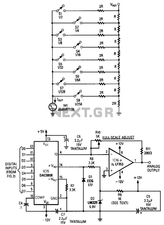
Figure A illustrates an R/2R resistor ladder. Each closed switch increases the current flow. A basic channel A/D converter is depicted in Figure B. The voltage reference (D2) is shared across all channels, although the value of the dropping...
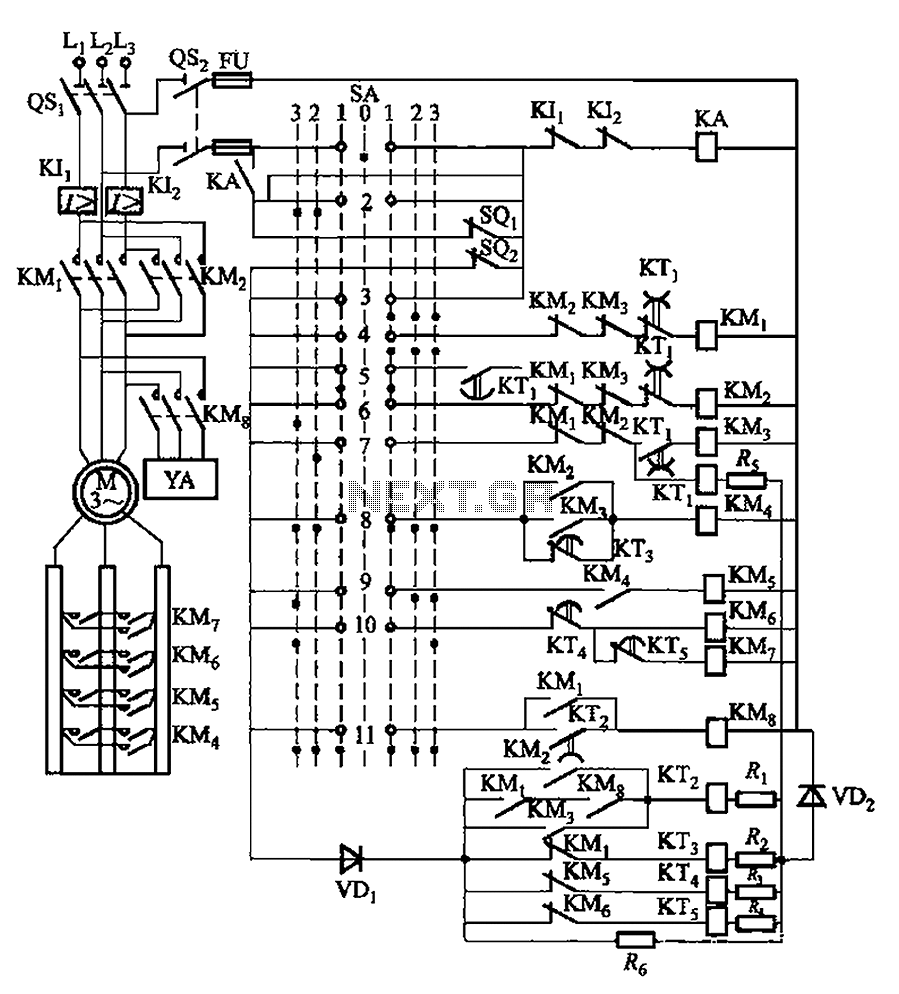
The system involves a master controller and a PQS1 Series Magnetic control panel, which includes a control circuit designed to manage the bridge crane hoist lifting mechanism. The master controller handle SA features seven positions: alongside the zero position,...
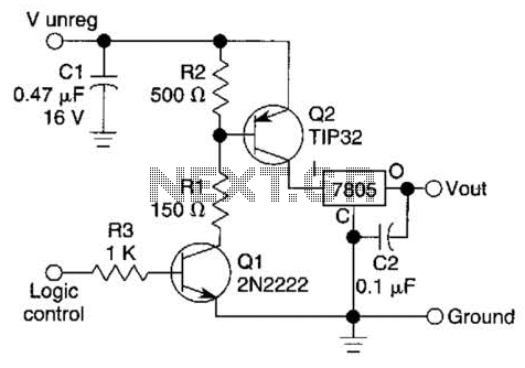
A logic level can control a 7805 regulator with this circuit. Q2 is a series switching transistor controlled by Q1. Q1 is turned on by a logic voltage to its base. This circuit utilizes a 7805 voltage regulator, which is...
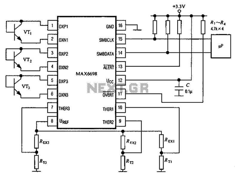
Channel 7 presents a circuit diagram of a smart temperature sensor using the MAX6698. This circuit includes three transistors (VT1, VT2, and VT3) and three thermistors (RT1, RT2, and RT3). An internal reference voltage source is provided via resistors...
Do you long for a beach holiday on a tropical island, but you don't have the necessary means? There is a solution: build the i-TRIXX surf simulator, put on your headphones, and escape from this mundane reality. Allow the...

The circuit is a high-power car audio amplifier schematic. It functions as a car audio amplifier using the PA02 and LH0101 integrated circuits (ICs). Each IC delivers an output power of 30W with an 8-ohm impedance. The part list...