
Lead-Acid Battery Charger Circuit

This circuit is designed to provide an efficient charging solution for car batteries by applying an initial voltage of 2.5V per cell. The charging process is characterized by a rapid voltage application, which facilitates a quick energy transfer to the battery. As the charging progresses, the charging current is dynamically adjusted, decreasing in magnitude as the battery approaches its full charge state. This behavior is essential for preventing overcharging, which can lead to battery damage and reduced lifespan.
The circuit may incorporate a voltage regulator to maintain the output voltage at 2.5V per cell, ensuring that the charging remains within safe limits. Additionally, a current sensing mechanism could be integrated to monitor the charging current in real-time. This feedback loop would allow for automatic adjustments to the charging current, ensuring that it tapers off as the battery's state of charge increases.
Further enhancements could include temperature monitoring to prevent overheating during the charging process. A microcontroller or dedicated charging IC could be employed to manage these functions, providing precise control over voltage and current delivery.
Overall, this circuit design focuses on efficient and safe charging practices, ensuring that the battery is charged quickly while minimizing the risk of damage due to excessive current or voltage.This circuit delivers an initial voltage of 2.5V per cell to rapidly charge a car battery. The charging current decreases as the battery charges and when t.. 🔗 External reference
Related Circuits
The output level was set to 3.8V peak to peak. The initial objective was to compare several different operational amplifiers (op-amps) before further optimizing the circuit. The op-amps evaluated were the TL072, LM4562, and OPA2134. The distortion spectra are...
In night photography, long exposures are common, sometimes lasting several seconds to several minutes. HDR techniques often require taking a series of nine or more photos. Holding a remote trigger for an extended period can be tedious, leading to...
Variable resistor R1 adjusts the light threshold at which the circuit triggers. R1's value is chosen to match the photocell's resistance at darkness. The circuit uses a CMOS 4001 IC. Gate U1a acts as the trigger, U1b and c...
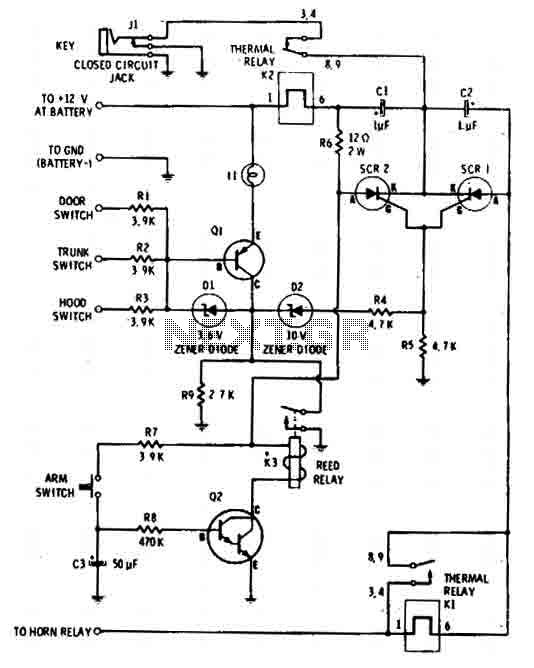
The car alarm is a straightforward circuit with fundamental features that monitor all entry points of the vehicle, such as doors, using switches. It operates with a single switch (the arm switch) that allows the circuit to remain inactive...
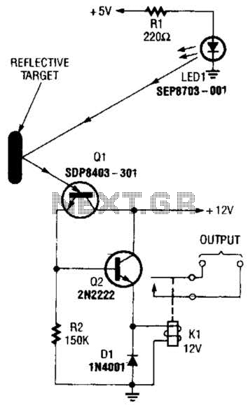
A reflector isolator detects the presence of an object by bouncing light off of it. This technique is useful in circuits that detect when an object is close enough to the sensor. A reflector isolator is a type of optical...

The application circuit operates the device as illustrated below, allowing for intermittent lighting in specific situations (e.g., during surgery). It utilizes an LCE module for blackout emergency lighting, which activates automatically after a power failure, ensuring uninterrupted illumination. In...