
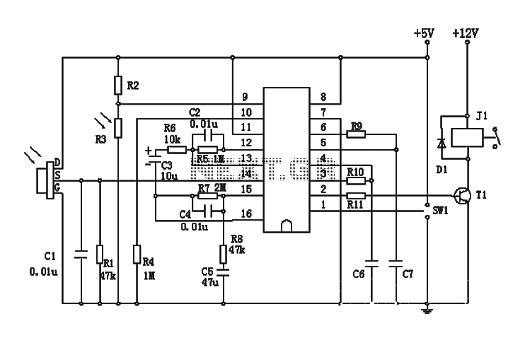
Light Detector Circuit

The described circuit utilizes a variable resistor, R1, which plays a crucial role in setting the light sensitivity threshold for triggering the circuit. The value of R1 is carefully selected to correspond with the resistance of a photocell in low light conditions, ensuring that the circuit activates when ambient light falls below a certain level.
The core of the circuit is built around the CMOS 4001 integrated circuit, which contains four NAND gates. In this configuration, gate U1a functions as the primary trigger for the circuit. It receives input from the voltage divider formed by the photocell and R1. When the light level drops and the voltage at the input of U1a reaches a specified threshold, the gate outputs a high signal, initiating the triggering sequence.
Subsequently, gates U1b and U1c are employed to create a latch mechanism. This latch maintains the output state even after the initial triggering condition has ceased, allowing the circuit to remain activated until it is intentionally reset. The reset function is facilitated by switch S1, which, when closed, clears the latch and returns the circuit to its original state.
The output of the latch is connected to a low power piezo buzzer, which serves as the output device. When the circuit is triggered, the buzzer emits sound, providing an audible indication of the light level falling below the defined threshold. This arrangement is particularly useful in applications such as automatic lighting systems or alarms that respond to changes in ambient light. The entire circuit is designed to operate efficiently with low power consumption, making it suitable for battery-operated devices.Variable resistor R1 adjusts the light threshold at which the circuit triggers. R1`s value is chosen to match the photocells resistance at darkness. The circuit uses a CMOS 4001 IC. Gate U1a acts as the trigger, U1b and c form a latch. S1 resets the circuit. The output device may be a low power piezo buzzer. 🔗 External reference
Related Circuits
The Motion Sensor Switch circuit is an automatic water sprinkler controlled by a motion sensor, with the option to incorporate an alarm or light function. Before starting the construction, it is advisable to contact a local electronics component vendor...
This class-D audio amplifier is suitable for TV and home stereo systems. The TDA7882 integrated circuit (IC) provides a class-D audio amplifier solution. Since this IC has a single channel output, two units are required for stereo applications. The...
This instructable will demonstrate how to interpret various circuit diagrams and assemble circuits on a breadboard. The process of reading circuit diagrams involves understanding the symbols and connections that represent electronic components and their interrelations. Key components include resistors, capacitors,...
This circuit is a 6-zone alarm system designed for independent operation, suitable for small office or home environments. It can be adapted to utilize a combination lock or keypad for setting and resetting the alarm. All zones, Z1 to...
The BISS0001 is a high-performance integrated circuit designed for sensor signal processing. When combined with pyroelectric infrared sensors and a minimal number of external components, it forms a passive pyroelectric infrared switch. This device can automatically and quickly activate...
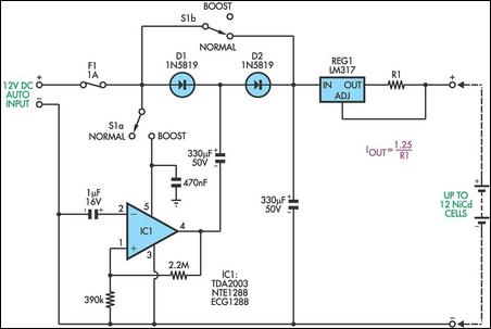
This circuit is designed to charge between one and twelve NiCd cells using a car battery. When switch S1 is in the "normal" position, it can charge up to six cells. The LM317 regulator functions as a simple current...