
lead acid battery charger schematic

The circuit operates as a battery charger with a focus on maintaining battery health through controlled charging parameters. The initial voltage of 2.5 V per cell is ideal for rapid charging, and the transition to a float voltage of 2.35 V per cell is critical for maintaining battery capacity without risk of damage. The LM301A comparator plays a vital role in monitoring the charging current, ensuring that the circuit responds dynamically to changes in battery state. The design incorporates resistors R1, R2, R3, and R4 to establish voltage references and current thresholds, while R1 specifically acts as a sensing resistor to monitor the charging current.
The inclusion of temperature compensation via the LM334 temperature sensor is essential for maintaining optimal charging conditions across varying environmental temperatures. The adjustment of R5 provides a means to calibrate the circuit for specific temperature ranges, ensuring consistent performance and battery safety.
The selection of voltage regulators (LM371, LM350, and LM338) allows the circuit to adapt to different current requirements, making it versatile for various battery sizes and types. The requirement for a filtered DC input voltage that exceeds the maximum output voltage by 3 V ensures reliable operation and stability of the charging process.
LED indicators provide immediate visual feedback regarding the circuit's status, enhancing user experience and safety. Overall, this circuit design emphasizes efficiency, safety, and adaptability, making it suitable for various battery charging applications.This circuit gives an initial voltage of 2. 5 V per cell at 25ƒ to rapidly charge the battery. The charging current decreases as the battery is charging, and when the current drops to 180 mA, the charging circuit reduces the output voltage of 2. 35 V per cell, leaving the battery in a fully charged state. This lower voltage prevents the battery fr om overcharging, which would shorten its life. The LM301A compares the voltage drop across R1 with an 18 mV reference set by R2. The comparator`s output controls the voltage regulator, forcing it to produce the lower float voltage when the battery-charging current, passing through R1, drops below 180 mA. The 150 mV difference in between the charge and float voltages is certainly set by the ratio of R3 to R4.
The LEDs present the state of the circuit. Temperature compensation assists stop overcharging, especially when a battery goes through wide temperature changes whilst becoming charged. The LM334 temperature sensor ought to be placed near or on the battery to lower the charging voltage by 4 mV/ƒ for each cell.
Because batteries require far more temperature compensation at lower temperatures, alter R5 to 30 © for a tc of -5 mV/ƒ per cell if application will see temperatures beneath -20ƒ. The charger`s input voltage need to be filtered dc that`s at the very least 3 V greater than the maximum required output voltage: approximately 2.
5 V per cell. Choose a regulator for the highest possible current required: LM371 for 2 A, LM350 for 4 A, or LM338 for 8 A. At 25ƒ and with no output load, adjust R7 for a VOUT of 7. 05 V, and adjust R8 for a VOUT of 14. 1V. 🔗 External reference
Related Circuits
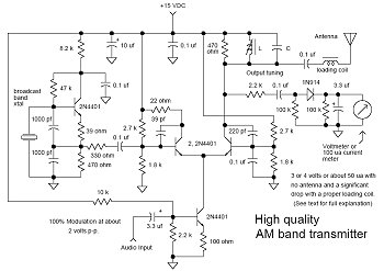
In many discussions of LPAM transmitter design, references to "the Wenzel circuit" or "the Wenzel transmitter" are common. These terms refer to a clever transmitter design that became popular in the mid-1990s and early 2000s for those interested in...
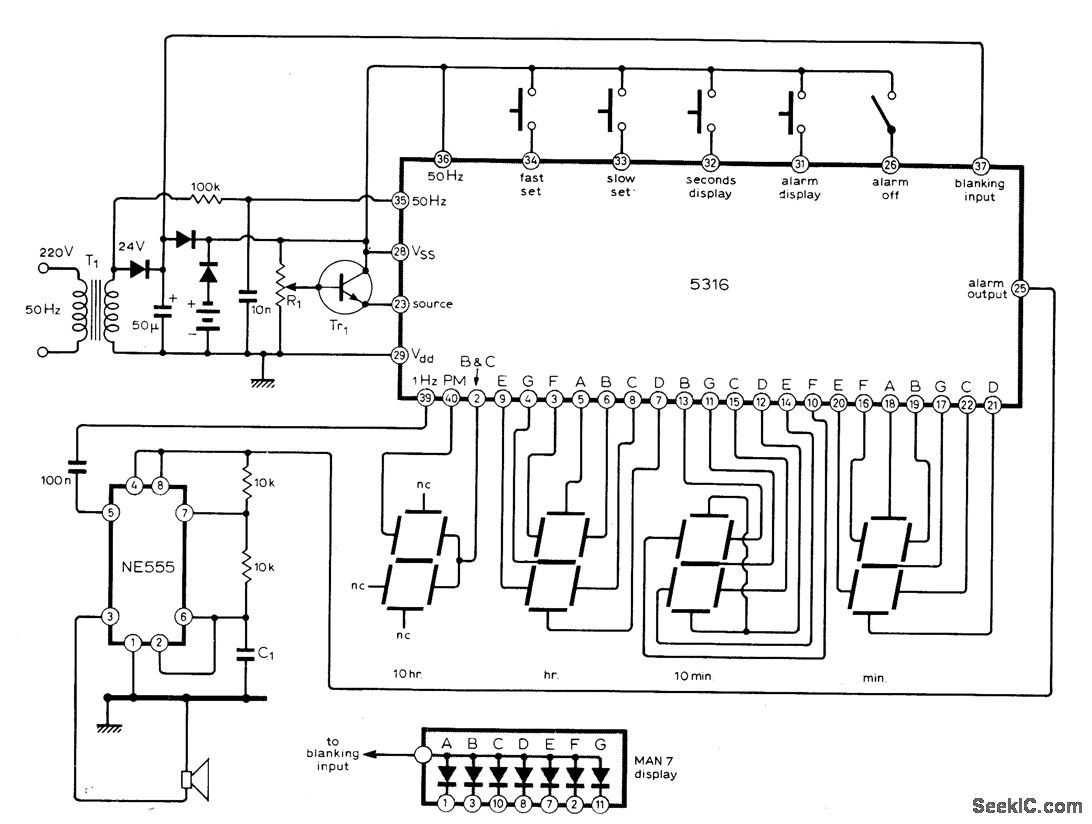
The circuit utilizes the MM5316 alarm-clock integrated circuit (IC), which is originally intended for driving LCD or fluorescent displays. In this implementation, it has been adapted for use with LED display diodes. The system is designed to operate on...
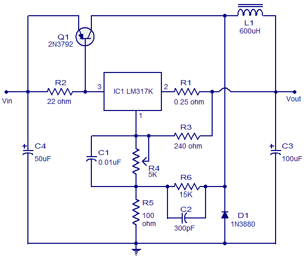
This circuit illustrates a 3A Switching Regulator Circuit based on the LM317K integrated circuit. It is designed to be simple and cost-effective. The 3A Switching Regulator Circuit utilizing the LM317K IC serves as a versatile voltage regulation solution, capable of...
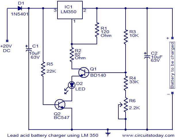
This circuit utilizes the IC LM350 for charging 12V lead-acid batteries, providing a constant voltage source with a negative temperature coefficient. The transistor Q1 (BD140) functions as a temperature sensor, while transistor Q2 prevents the battery from discharging through...
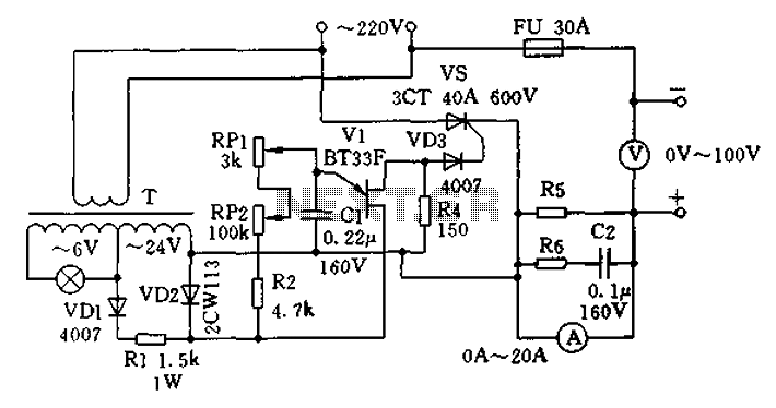
The charging apparatus depicted in the schematic circuit has a maximum output current of 20A and a maximum charging voltage of 80V. It can be adjusted starting from 0V, making it suitable for charging various types of batteries. The...
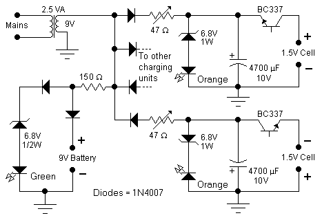
This circuit was specifically designed to recharge alkaline cells. The unusual connection of the transistor in each charging unit will cause it to oscillate, on and off, thus transferring the charge accumulated in the capacitor to the cell. The...