
ALKALINE CHARGER

The circuit for recharging alkaline cells utilizes a unique configuration of transistors that allows for an oscillating charge transfer mechanism. This design features a charging unit that consists of a capacitor, which stores energy, and a transistor that is configured to operate in a feedback loop. The oscillation generated by the transistor is essential for the effective transfer of energy from the capacitor to the cell being charged.
The blinking orange LED serves as an indicator of the charging status. Under normal conditions, when charging a cell with a nominal voltage of 1.37V, the LED will blink approximately five times per second. In the case of a deeply discharged cell, the LED will blink at a higher frequency, indicating that the circuit is actively charging the cell. As the cell approaches full charge, the blinking rate will gradually decrease until it ceases, signaling that the cell is fully charged.
The circuit is designed to allow for trickle charging, which maintains the cell voltage at around 1.6V. This feature is crucial for preventing overcharging and ensuring the longevity of the alkaline cell. To calibrate the circuit for optimal performance, it is necessary to connect a fresh, unused alkaline cell and adjust the trimmer potentiometer. This adjustment should be made until the oscillations are observed, followed by a slight reduction in the adjustment until the oscillations cease. This process ensures that the circuit is properly tuned for the specific characteristics of the alkaline cell being charged.
Only the specified transistors should be employed in the circuit to ensure reliability and efficiency. The choice of components is critical, as they must be capable of handling the oscillation frequency and the charging current without overheating or failing. Proper attention to the circuit layout and component selection will enhance the overall performance and safety of the alkaline cell charging system.This circuit was specifically designed to recharge alkaline cells. The unusual connection of the transistor in each charging unit will cause it to oscillate, on and off, thus transferring the charge accumulated in the capacitor to the cell. The orange LED will blink for around 5 times a second for a 1.37V cell. For a totally discharged cell the blinking is faster but it will decrease until it will come to a stop when the cell is charged.
You may leave the cell in the charger as it will trickle charge and keep it at around 1.6V. To set the correct voltage you have to connect a fresh, unused cell and adjust the trimmer until oscillations set in, then go back a little until no oscillation is present and the circuit is ready to operate. You should use only the specified transistors, 🔗 External reference
Related Circuits
The USB charger power supply is designed for use in MP3 and MP4 chargers. It accepts an input of AC 160-240V at 50/60Hz and has a rated output of DC 5V at 250mA. For applications requiring a long-term higher...
This circuit will charge a 12v battery (10 NiMH cells) @ approx 220mA. It is a very simple circuit but requires correct setting up. The circuit is designed around a 12vDC, 500mA plug pack. This type of plug pack...
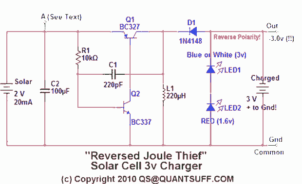
This design presents an innovative approach to the Joule Thief (JT) circuit typically utilized in garden lights. Instead of directly charging a 1.2V battery from the solar cell and converting the power to operate a 3-volt LED, this circuit...
The ASUS Eee is an ultra-portable notebook that meets the essential needs of tech enthusiasts while maintaining excellent build quality and affordability. In New Zealand, it can be purchased exclusively from DSE, where it is competitively priced compared to...
Before starting a project of this nature, it is crucial to remember that mains voltage is hazardous. If there is any uncertainty regarding the procedure, it is advisable to consult someone with the appropriate skills or refrain from proceeding...
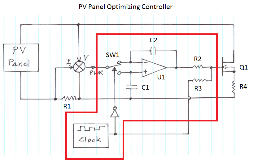
The figure illustrates the voltage-current (V-I) curve for a typical solar panel (Sharp ND-224U1F) and its output power under varying lighting conditions. The solar panel operates as a constant current source at high currents and as a voltage source...