
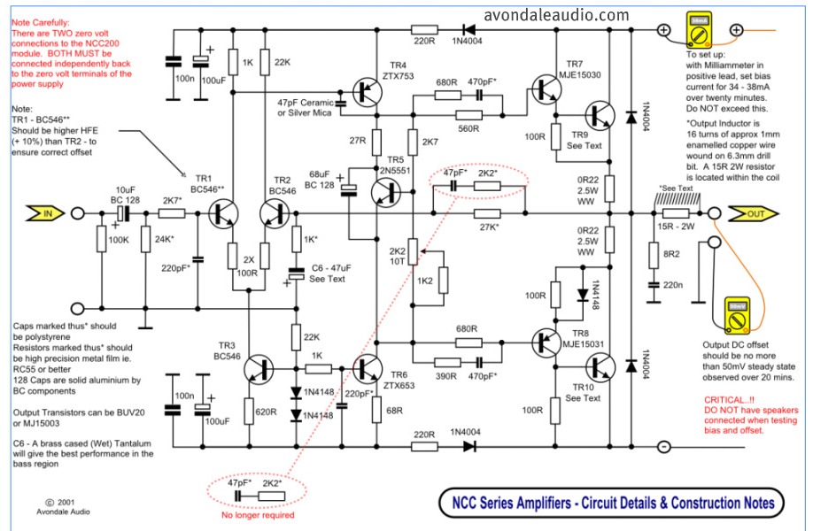
Amplifier Schematic Diagram

The circuit described is designed to modify the time constant in an RC (resistor-capacitor) circuit, which directly affects the ramp time of the output voltage across the capacitor. The time constant, denoted as τ (tau), is calculated using the formula τ = R × C, where R is the resistance in ohms and C is the capacitance in farads. By adjusting either the resistance (R) or the capacitance (C), the time constant can be increased or decreased, resulting in a longer or shorter ramp time, respectively.
In this configuration, a transistor can be utilized to control the resistance dynamically. For instance, using a variable resistor (potentiometer) or a transistor in a feedback loop allows for real-time adjustments to the resistance value. The capacitor in the circuit serves to store charge and smooth out voltage changes, while the resistor determines how quickly the capacitor charges and discharges.
The implementation of this circuit can be particularly useful in applications such as timing circuits, signal processing, or any system requiring precise control over voltage ramping characteristics. Proper selection of component values is crucial to achieving the desired time constant and ensuring that the circuit operates within its intended parameters.Function: to increase or decrease the time constant with the capacitor, which increases or decreases the ramp time. Component: Transistor, Capacitor, Resistor, .. 🔗 External reference
Related Circuits
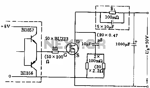
The circuit employs 50 BUZ23 field effect transistors (FETs) arranged in parallel, with a tube blocking voltage of 100V. The control power required is minimal, eliminating the risks associated with second breakdown and the positive temperature coefficient phenomenon in...
This is a simple circuit that features high-performance power amplifiers. The power amplifier is available as a PCB, along with a complete list of components. The described circuit utilizes high-performance power amplifiers, which are essential for applications requiring significant signal...
While conversing with a distant subscriber on the telephone, it is common to experience frustration due to faint audio that is barely intelligible. To address this issue, an inexpensive amplifier circuit is proposed. This circuit can be easily assembled...
Free domains and hosting with up to 1GB of disk space, unlimited transfer, and access to PHP as well as 5 MySQL databases. The maximum size of a single file is not limited. This service offers a robust web hosting...
The LH0024 is a small signal integrated circuit (IC) designed for general-purpose switching and amplification due to its low voltage characteristics. Additionally, it utilizes three 1N4148 silicon small signal diodes, which are planar epitaxial devices used for fast switching...
Parts List The circuit consists of a preamplifier, tone controls, and a regulated DC power supply, providing a power output of 18 Watts for an 8 Ohm load. The circuit design includes three main components: a preamplifier, tone control circuitry,...