
LED audio peak level

The peak level indicator circuit employs a CMOS inverting Schmitt trigger (74C14) to effectively monitor signal levels and provide visual feedback through an LED. The circuit is designed to respond accurately to transient signals, making it suitable for audio applications such as tape recorders and mixing consoles.
The input stage of the circuit features a half-wave rectifier (D1) that converts the incoming AC signal into a unidirectional voltage. This rectified voltage is then fed into a resistor (R1), which acts as a voltage divider, setting the threshold at which the Schmitt trigger activates. The Schmitt trigger has a defined upper threshold, which is influenced by the supply voltage; for a 5V supply, this threshold is set at 3.6V. When the voltage across R1 exceeds this threshold, the output of the second Schmitt trigger transitions to a high logic level (logic [H]).
Feedback is provided to the input of the second Schmitt trigger through a capacitor (C2). This feedback mechanism allows the circuit to maintain the high output state for a brief period after the input signal has dropped, effectively capturing short-duration peaks. The duration for which the output remains high is determined by the RC time constant formed by R1 and C2.
When the output of the second Schmitt trigger is high, the output of the third Schmitt trigger will be low (logic L), which in turn activates the LED (D4). This LED serves as a visual indicator that the input signal has exceeded the defined threshold, alerting the user to potential clipping or distortion in the audio signal.
Adjustment of the trimmer resistor (TR1) allows for fine-tuning of the maximum input level that the peak indicator will respond to, providing flexibility in various applications. The overall design ensures that the peak level indicator is not only sensitive to short signals but also maintains a high input impedance, minimizing loading effects on the source signal.
The component selection includes a 1MΩ resistor (R1), a 150nF capacitor (C2), a 100nF capacitor (C1), a series of 1N4148 diodes (D1-2-3), a red LED (D4), and a 1MΩ trimmer (TR1), all of which contribute to the circuit's performance and reliability.A peak level indicator when a signal exceeds a certain maximum value. It can be quite useful, for instance, with tape recorders, mixing consoles etc. One of the most important requirements of a peak level indicator is that it should respond to very short signals. The circuit is built using a CMOS inverting Schmitt trigger type 74C14. The input impedance of the peak indicator is fairly high. The value depends to some extent on the position of TR1. The unit functions as follows. The input is half- wave rectified by D1. When the voltage across R1 exceeds the upper trigger threshold, a logic [H] is produced at the output of the second Schmitt trigger.
The trigger threshold depends on the supply voltage. With a 5V supply the trigger level is 3.6V. The positive pulse at the output of the second trigger is feedback to the input via C2. If the input signal was very short, the logic H level will be maintained during the charging time of C2. This time is determined by the values of C2 and R1. During this time the output of the third trigger is logic L, so that LED D4 lights up as an indication that the level of the input signal is too high.
The TR1 trimmer is adjusted to the maximum desired level that the peak indicator should begin to function at. Part List R1=1Mohms C2=150nF 100V MKT IC1=74C14 TR1=1Mohms trimmer D1-2-3=1N4148 C1=100nF 100V MKT D4=RED LED DIODE
🔗 External reference
Related Circuits
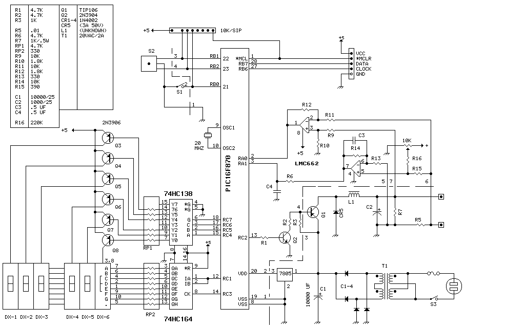
This unit delivers 0 to 20 volts at up to 4 amps in 0.1 volt increments. The entire device runs on a PIC16F870 (about $3 in small quantities). This is basically a switching power supply with the voltage regulation...
The first reverberator presented is based on the TDA1022, which is the most commonly used BBD (Bucket Brigade Device). Adjustments for proper functionality of the reverberator are required before connecting the power supply. The TDA1022 is a versatile BBD that...
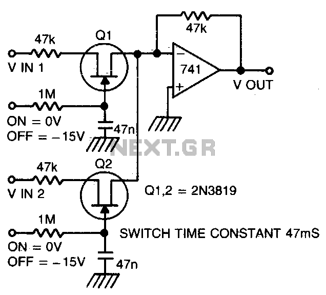
Two or more signals can be switched and/or mixed without annoying clicks by using FETs and a low input-impedance op amp circuit. The circuit design utilizes Field Effect Transistors (FETs) to facilitate the switching and mixing of multiple signals while...
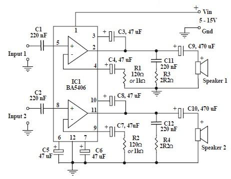
This circuit is based on the BA5406 audio integrated circuit and is capable of providing a maximum output power of 3 watts per channel. This audio circuit is designed for various applications requiring amplified sound output. The BA5406 is a...

This circuit operates effectively across a broad frequency spectrum. XTAL 1 serves as a fundamental-frequency crystal. Tl and CI are adjusted to match the input frequency. This circuit can be utilized as a straightforward shortwave converter for AM radios,...
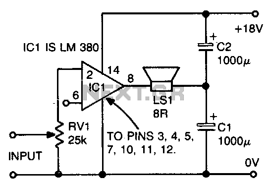
The ground side of the speaker is connected to the junction of two equal high-value capacitors (1000 µF is typical) across the supply. The amplifier output voltage will be Vs/2, and the voltage across CI (if CI and C2...