
TDA1022 Audio Reverberator Circuit
The TDA1022 is a versatile BBD that operates effectively in audio processing applications, particularly for creating reverb effects. It is designed to handle low-frequency signals, making it suitable for musical instruments and vocal processing. The reverberator circuit using the TDA1022 typically includes several key components: the BBD itself, a clock generator for timing control, and various passive components such as resistors and capacitors that dictate the delay time and feedback characteristics.
To ensure proper functionality, the circuit should be configured with the appropriate power supply voltage as specified in the TDA1022 datasheet, usually around 9V to 15V. Additionally, adjustments may include setting the input and output levels to prevent distortion or clipping, as well as tuning the feedback loop to achieve the desired reverberation effect. The integration of potentiometers in the feedback path can allow for real-time adjustments of the reverb depth.
The schematic will typically feature an input stage where the audio signal is fed into the TDA1022. The output stage will then convert the processed signal back to a suitable level for further amplification or mixing. Care should be taken to layout the PCB to minimize noise and interference, especially in the clock circuit, as timing inaccuracies can adversely affect the reverb quality.
Overall, the TDA1022-based reverberator design exemplifies a classic approach to audio effects, combining analog components to produce a rich, spacious sound that enhances musical performances. Proper tuning and adjustments are essential for optimal performance, ensuring that the reverberation effect complements the source material effectively.The first reverberator we present is based on TDA1022, the most used BBD. Reverberator adjustements for proper functionality Before we connect the power su.. 🔗 External reference
Related Circuits
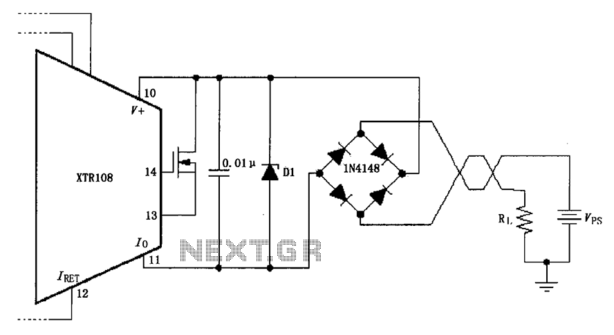
The circuit utilizes a Zener diode (D1) for overvoltage protection and a diode rectifier bridge for reverse voltage protection. The 1.4V drop across the diodes will result in a maximum voltage loss, meaning that the supply voltage (VPS) must...
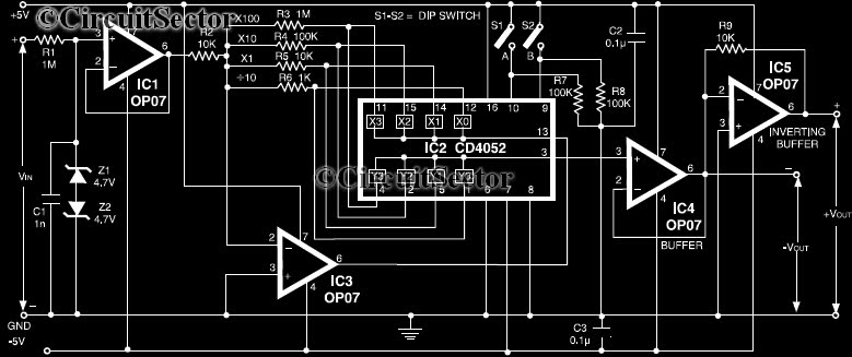
This circuit is a precision amplifier with digital control, designed for signal conditioning of low-output transducers operating in the millivolt range. The resistors R3 to R6 can be user-selected, with values ranging from 1 kilo-ohm to 1 mega-ohm, allowing...
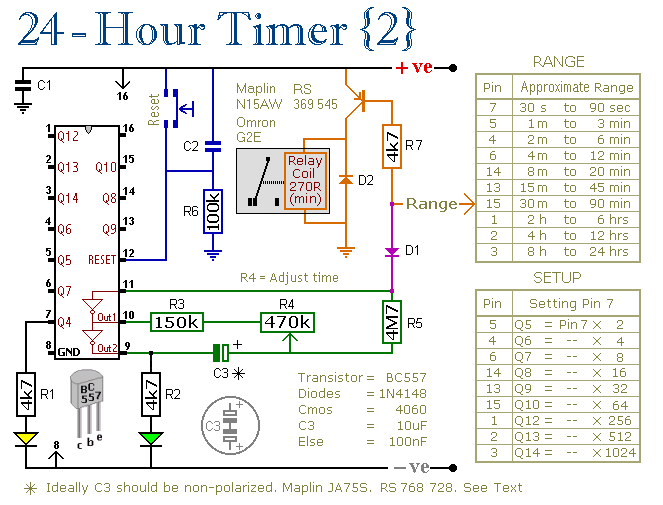
These two circuits are multi-range timers that offer periods of up to 24 hours and beyond. They can function as repeating timers or single-shot timers. Both circuits are fundamentally the same, with the primary distinction being their behavior in...
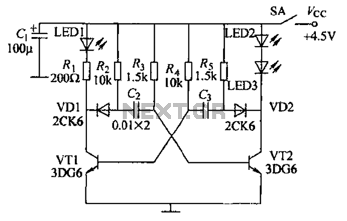
Transistors VT1, VT2, and associated RC components are configured to form a multivibrator. The multivibrator operates with resistors Ra and R4 serving as base bias resistors for VT2 and VT1, respectively. When the switch SA is closed after applying...

A Field Effect Transistor (FET) is an amplifying device where the output current is influenced by the input voltage. The FET preamplifier described here is sensitive. The Field Effect Transistor (FET) operates by utilizing an electric field to control the...
This document outlines the theory behind a high-speed control scheme for an LED display screen circuit. The circuit utilizes the MCS51 series microcontroller to manage the LED display. A 62512 random access memory (RAM) is employed for data storage,...