
LED Bike Light Circuit Project

The circuit operates by converting the alternating current generated by the dynamo into a usable voltage for powering LEDs. The BD911 transistors serve as the main switching elements in the power supply circuit, allowing for efficient control of the LED lighting system. The astable multivibrator configuration ensures that the lights alternate, enhancing visibility for safety while cycling. The RC timing components (R2, R3, C3, and C4) are critical in determining the blink rate of the LEDs, which can be adjusted by modifying the resistor or capacitor values.
The prototyping board design includes six LEDs arranged in pairs, with each pair connected to a resistor to limit current and prevent damage to the LEDs. The choice of white LEDs for the front and red for the rear is standard practice in bicycle lighting to ensure proper visibility and compliance with safety regulations. The placement of the PCB under the seat not only protects it from environmental factors but also helps in maintaining a clean wiring layout.
For future iterations, the addition of an on/off switch would enhance usability, allowing the user to control the lighting system more conveniently. Transitioning to surface-mount devices (SMD) could significantly reduce the size of the circuit, allowing for more flexible placement options and reducing the amount of wiring needed, which could improve the overall reliability and aesthetics of the installation.First I bought another front wheel, one which has a dynamo already built in the hub. This supplied a nice sine wave of 30 Vpp (at no load). With this knowledge I designed a simple power supply. The transistors that are used are type BD911. These are a bit of an over-kill, but there were plenty of these at my school, so that is why I used them. Something a little smaller will also work. The power supply is connected to an astable multi-vibrator. This alternately drives the front light and the rear light. The frequency is determined by the RC time-constant of R3 and C3, and R2 and C4. This time can be calculated with the formula: t = R3G—C3 = 20G—103G—10G—10-6 = 0. 2 s You can use a 22k (common value) for R2 and R3, that doesn`t make much difference. On a small piece of prototyping board are six LEDs with a voltage dropping resistor in series with each pair of LEDs. Such a PCB is used for both the front and the rear of the bike. Of course, you use white LEDs for the front and red ones for the rear. The PCB with the main circuit is mounted under the seat, where it is safe and has been working for more than a year now.
There are a few things I would change for the next revision. An on/off switch would be nice. And if the whole circuit was built with SMD parts it could be mounted near the front light. This would also be more convenient when routing the wiring. Now the cable from the dynamo goes all the way to the seat and from there to the front and rear lights. 🔗 External reference
Related Circuits
This is a power-on time delay relay circuit that utilizes the emitter/base breakdown voltage of a standard bipolar transistor. The reverse-connected emitter/base junction of a 2N3904 transistor functions as an 8-volt zener diode, establishing a higher turn-on voltage for...
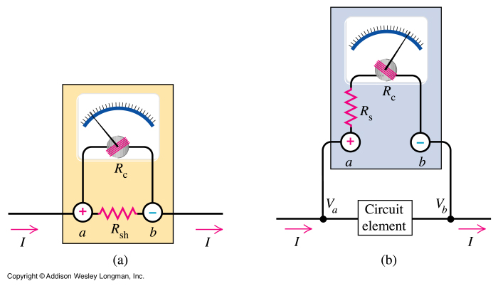
Electron trajectories in a conductor are depicted in the diagrams below. When no electric field is present inside a conducting material, electrons move randomly. However, when an electric field is applied, the electric force F = qE induces a...
The most extreme option would be to supply power through a battery pack. A more plausible source would be the car's battery. However, since the objective of the circuit is to activate the buzzer when the headlights are on,...
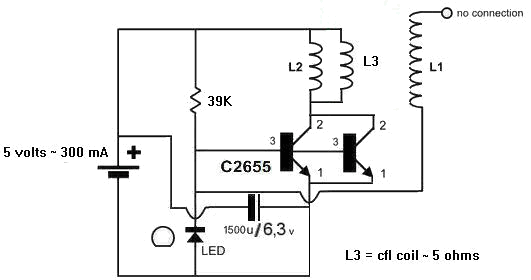
A 1N4148 diode and a 1-megohm resistor are included in the circuit. The inquiry pertains to how to power LED(s) using a 1.5-volt battery. There is also a question regarding the role of an additional coil, L3, and its...
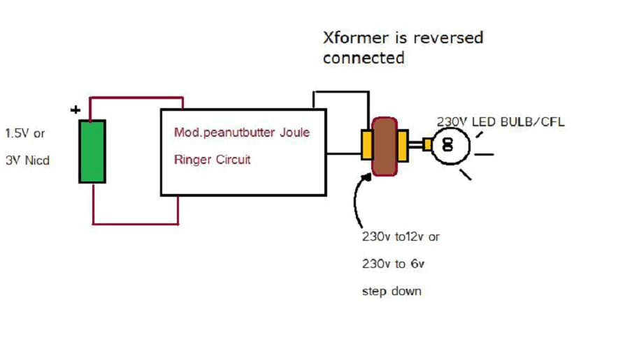
Various threads on ringer circuits have been observed, showcasing multiple variants, particularly concerning the types of transformers utilized, such as air core and step-down transformers. One notable circuit is the 12V-to-120V configuration, which employs a joule ringer that utilizes...
This precise one-pulse-per-second clock is constructed using a few common components and is driven by a 50 or 60 Hertz mains supply without any direct connection to it. A beep or a metronome-like click, along with a visible flash,...