
One second Audible Clock Circuit Schematic

The one-pulse-per-second clock circuit is designed for high reliability and ease of assembly. The central component, the CMOS 4024 counter/divider, is a versatile device capable of dividing input frequencies by whole numbers. This feature allows the circuit to produce a precise one-second pulse from the mains frequency with minimal external components. The high input impedance at pin #1 ensures that the circuit can be activated by very weak signals, making it suitable for various environments.
The use of diodes in the circuit serves multiple purposes, including signal rectification and protection. The arrangement of three diodes provides necessary isolation and ensures that the circuit operates correctly regardless of the mains frequency. The modification for 60Hz operation is straightforward, requiring only a simple reconfiguration of the connections.
The optional visual display, consisting of a light-emitting diode (LED) and a resistor, enhances the circuit's functionality by providing a visual indication of the one-second pulse. The choice of resistor value is crucial; for battery voltages of 9V or higher, using a 1K resistor prevents excessive current flow through the LED, ensuring longevity and consistent performance.
Overall, this circuit design demonstrates a practical approach to creating a precise timing signal suitable for various applications, from simple timers to more complex delay mechanisms. Its reliance on common components ensures accessibility for hobbyists and professionals alike, while the straightforward modifications allow for adaptability to different mains frequencies.This accurate one-pulse-per-second clock is made with a few common parts and driven from a 50 or 60 Hertz mains supply but with no direct connection to it. A beep or metronome-like click and/or a visible flash, will beat the one-second time and can be useful in many applications in which some sort of time-delay counting in seconds is desirable.
Th e circuit is formed by a CMos 4024 counter/divider chip and 3 diodes, arranged to divide the frequency of the input signal at pin #1 by 50 (or 60, see Notes). The input impedance at pin #1 is very hight, so simply touching the pin (or a short track or piece of wire connected to it) is usually enough to provide the necessary input signal.
Another way to provide an input signal consists in a piece of wire wrapped several times around any convenient mains cable or transformer. No other connection is necessary. To allow precise circuit operation in places where the mains supply frequency is rated at 60Hz, the circuit must be modified as follows: disconnect the Cathode of D1 from pin #11 of IC1 and connect it to pin #9.
Add a further 1N4148 diode, connecting its Anode to R1 and the Cathode to pin #6 of IC1: that`s all! The visual display, formed by D4 and R3 is optional. Please note that R3 value shown in the Parts list is suited to low battery voltages. If 9V or higher voltages are used, change its value to 1K. 🔗 External reference
Related Circuits
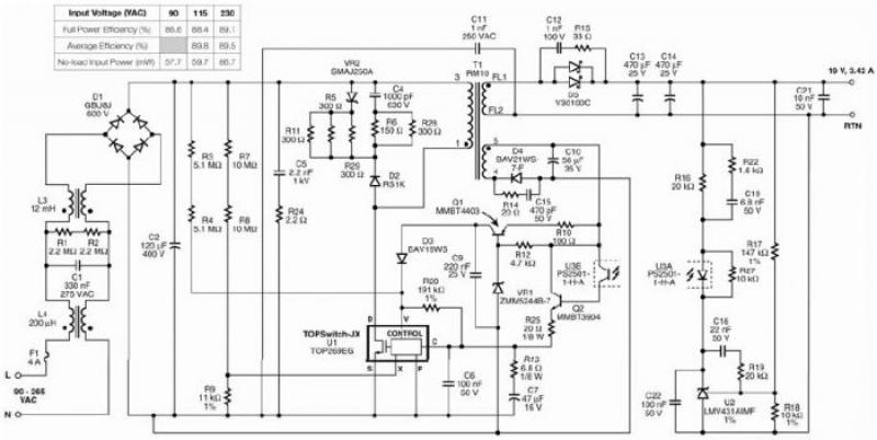
The TOP269EG off-line switcher integrated circuit (IC), designated as U1, can be utilized in a flyback configuration to create a simple and highly efficient power adapter for notebook laptops. The TOP269EG features an integrated 725 V MOSFET and a...
This is a simple scheme for a bridge oscillator. It provides a nice sinusoidal signal. This type of oscillator uses an op-amp. The weakening of the oscillating member (R1, R2, C1, C2) is 3x. To compensate, the attenuated signal...
This modification is to be performed at your own risk, and there is no guarantee that it will work for you. Improper installation of this design may result in damage to you and/or your laserdisc player. This website does...
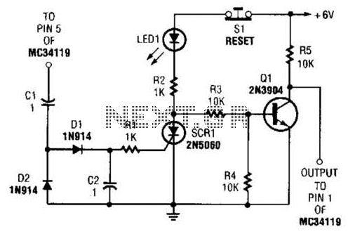
The ear protector is a peak audio detector and shutdown circuit that disables the amplifier through its chip-disable input when the output volume of the amplifier reaches a predetermined level. Although designed for the MC34119 amplifier, the circuit should...
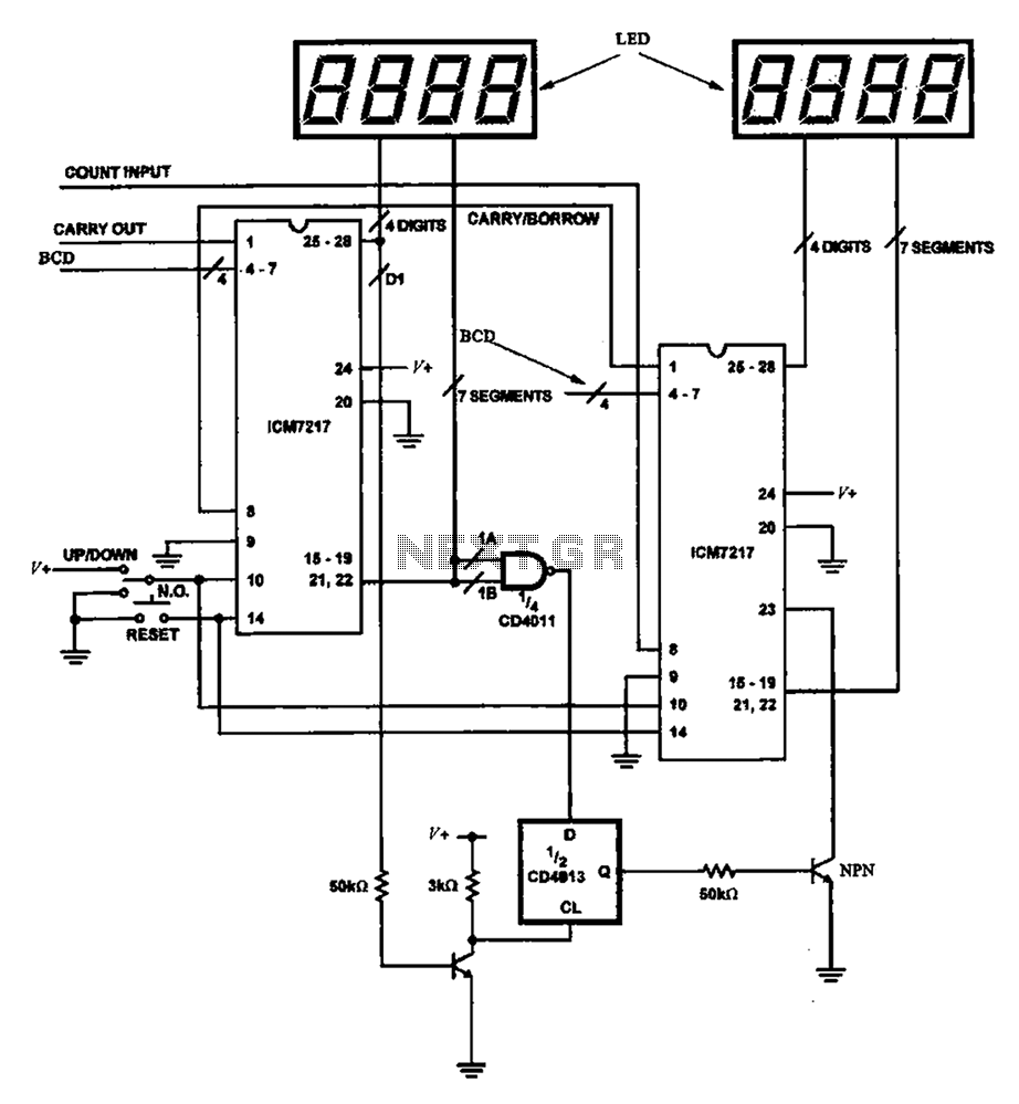
Figure 8 illustrates a potential digital counter circuit. This circuit employs two ICM7217 integrated circuits, with each controlling four digital display tubes. The digital counter circuit primarily utilizes the ICM7217, a highly integrated chip designed for driving seven-segment displays. Each...
Open and short circuit tests on a transformer are conducted to determine the equivalent circuit of the transformer, assess its voltage regulation, and evaluate its efficiency. The open circuit test is performed by applying the rated voltage to the primary...