
led blinking using avr studio 5

The ATmega32 microcontroller is a member of the AVR family, widely utilized in embedded systems due to its ease of use and versatility. This tutorial serves as an introductory guide for new users, providing a simple program that demonstrates fundamental concepts of microcontroller programming and operation.
The "Hello World" program typically involves configuring the microcontroller to perform basic input and output operations, such as blinking an LED. This exercise helps users understand the essential components of microcontroller programming, including setting up the development environment, writing code, and uploading it to the microcontroller.
To implement this program, the following steps are generally involved:
1. **Development Environment Setup**: Install the necessary software tools, such as Atmel Studio or Arduino IDE, which are compatible with the ATmega32 microcontroller.
2. **Circuit Design**: Create a simple circuit where an LED is connected to one of the digital output pins of the ATmega32. A current-limiting resistor should be included in series with the LED to prevent damage.
3. **Code Writing**: Write a simple program in C or Assembly language that initializes the microcontroller, configures the designated pin as an output, and toggles the LED state in a loop. This typically involves the following steps:
- Setting the Data Direction Register (DDR) for the pin connected to the LED.
- Using a loop to turn the LED on and off with a delay.
4. **Compiling and Uploading**: Compile the code using the selected development environment and upload it to the ATmega32 microcontroller using a programmer.
5. **Testing**: Power the circuit and observe the LED blinking, confirming that the microcontroller is functioning as intended.
This basic exercise not only introduces beginners to the ATmega32 microcontroller but also lays the groundwork for more complex projects involving sensors, communication protocols, and other peripherals in future applications.This is a very basic tutorial for atmega32 microcontroller beginners to get started. You can call this little program as Hello World for atmega. 🔗 External reference
Related Circuits
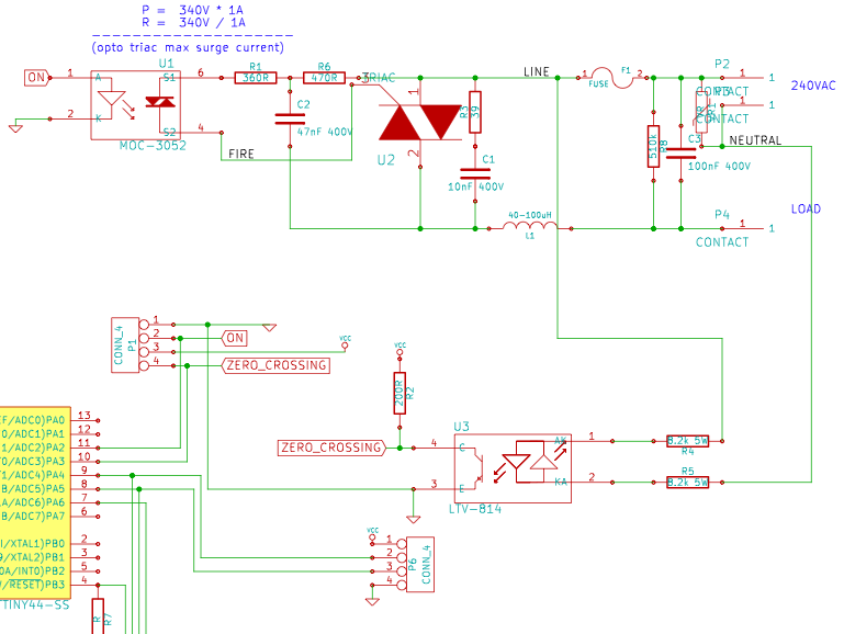
The resistance of the heater is constructed using 9 Ω nichrome wire with a diameter of 3 mm. When supplied with 240V (rms) voltage, this configuration results in a current of 25A (rms). Access to a mains line that...

The circuit diagram represents a simple parking sensor system that measures the distance between the rear bumper of a vehicle and obstacles located behind it. The schematic consists of two main components: the transmitter and the receiver. The distance...
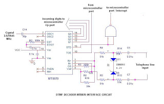
This is a straightforward circuit utilizing the DTMF decoder MT8870 (or CM8870). As illustrated in the circuit, an interrupt will be generated (if the NAND output is connected to the INT of the microcontroller) whenever a call is received...
This may be the simplest LED flasher circuit you can build, with the notable exclusion of LEDs with integrated flashing circuits. This might be a good replacement for the LM3909 in some applications. Take a close look. Only the...

The alternating LED flasher is a two-transistor oscillator with LEDs connected to the collector of each transistor, allowing them to light in sync with the circuit's oscillations. The alternating LED flasher circuit utilizes a two-transistor oscillator configuration, which is a...

Figure 3 illustrates a circuit featuring the OP37, which is a multi-preamplifier configuration. The OP37 offers superior performance compared to the NE5534 integrated operational amplifier, as indicated in Table 3-3, which contrasts the parameters of both circuits. The table...