
One transistor LED Flasher


The LED flasher circuit described operates on a simple principle of charging and discharging a capacitor through a transistor. The 2N2222 NPN transistor is used in this circuit with its base lead removed, allowing for a direct connection between the emitter and collector. This configuration exploits the transistor's ability to switch on and off based on the voltage across the capacitor, which is charged through a 1kΩ resistor.
Initially, the 330 µF capacitor charges until the voltage reaches approximately 9 volts. At this threshold, the emitter-base junction of the transistor enters avalanche breakdown, causing the transistor to turn on rapidly. This results in the capacitor discharging through the LED and the 100 Ω current-limiting resistor, producing a flash of light. The current flowing through the circuit peaks at around 26 mA, as indicated by the oscilloscope measurements. Once the discharge current drops to 6 mA, the transistor turns off, halting the conduction and allowing the capacitor to recharge, thereby initiating a new cycle.
The choice of charging resistor is critical for the operation of the circuit. If the resistance is too low, the capacitor will charge too quickly, preventing the transistor from turning off. Conversely, if the resistance is too high, the capacitor may not charge sufficiently to turn the transistor on. The circuit can accommodate various LED types, including those with integrated resistors, but caution should be exercised regarding the peak current to avoid damaging the LED.
The oscillation frequency of the circuit can be adjusted by varying the capacitor's value; a smaller capacitor will yield faster oscillation and shorter flash durations. The 2N2222 transistor is noted for its reliability in this application, although other transistor types may exhibit unpredictable behavior. This LED flasher circuit represents a practical and simple approach to creating flashing LED effects, suitable for various applications.This may be the simplest LED flasher circuit you can build, with the notable exclusion of LED's with integrated flashing circuits. This might be a good replacement for the LM3909 in some applications. Take a close look. Only the emitter and collector leads of the 2N2222 are connected. The base lead was cut off. The LED is from a string of Christmas lights and it has an integrated 100 Ohm resistor. This LED flasher occurred to me while reading about negative resistance in transistors. In this implementation, a common NPN transistor is used. In the circuit, a 1k resistor charged the 330 uf capacitor until the voltage became large enough to get the emitter-base junction to avelanche.
If the resistor that charges the capacitor is too low in value (or if the power supply voltage is too high), the current through the transistor will not become low enough for the transistor to turn off. If the resistor that charges the capacitor is too high in value (or the power supply voltage is too low), the capacitor will not be able to charge to a high enough voltage to enable the transistor to turn on.
This is because the transistor draws as small amount of current before switching on. In the oscilloscope image, it can be seen that the peak voltage (yellow trace) was a little bit less than 9 volts. At this point transistor turned on quickly and partially discharged the 330 uf capacitor through the LED and the 100 Ohm current limiting resistor.
The current wavform, which is the voltage drop across the 100 Ohm resistor, is shown in the blue trace on the scope image. Peak current was 26 milliamps, and the transistor continued to discharge the capacitor until conduction suddenly ceased at 6 milliamps (Many thanks to Luke in Australia for pointing out the correct current).
After the transistor stopped conducting, the capacitor began charging again, thus starting a new cycle. I've tried this with red LED's with and without integrated current limiting resistors, and on some while LED's.
This circuit can be built without the current limiting resistor, but if you choose to do so, please be aware that the peak currents may be high enough to shorten the life of the LED. The capacitor value isn't critical. A lower value will result in faster oscillation and shorter flashes. The 2N2222 NPN transistor seems to work reliably in this circuit. Other transistors may be more tempermental, and others might not work at all. 🔗 External reference
Related Circuits
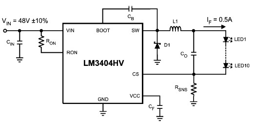
The LM3404 is a monolithic switching regulator that can be utilized to design a simple constant current driver for high-power LEDs. This LED driver project is suitable for automotive, industrial, and general lighting applications. Hysteretic control of the on-time,...
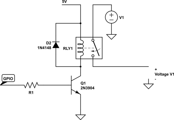
A couple of motors were salvaged from an old printer, and there is uncertainty regarding how to connect them to a breadboard and subsequently to a Raspberry Pi. A cobbler kit for the Raspberry Pi is available for this...
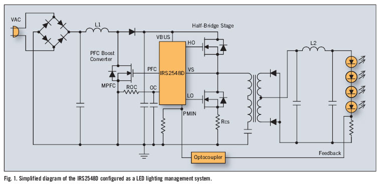
There is significant sensitivity to operating costs when managing high-powered commercial lighting. In these applications, there is a heightened focus on energy efficiency and AC line power factor, as these parameters influence operating expenses. Electric utilities impose additional charges...
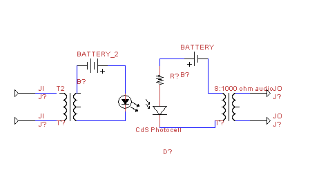
This circuit transmits audio information using light waves. It employs amplitude modulation (AM) to vary the intensity of an LED, which is detected by a cadmium sulfide photocell that changes its resistance based on light intensity. The circuit includes...
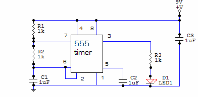
This circuit is built around one of the most popular timer integrated circuits, the 555 timer. It will flash the LED on and off at regular intervals. From left to right, the two resistors and the capacitor set the...

The following circuit illustrates an RF amplifier designed for FM frequencies ranging from 88 to 108 MHz with a broadband configuration. This circuit utilizes the BLV10 transistor. The RF amplifier circuit operates within the FM broadcast band, which is crucial...