
LED Boost Circuit

1. Trim the board to the final size you want before assembly. The board may be sawn, sanded, or filed to shape. It is designed to be round should you want, a bit less than the diameter of an AA cell.
The circuit described is a boost driver designed to convert low input voltages into a higher output voltage suitable for driving LED lights. The operational voltage range of 0.8 to 3 Volts allows for flexibility in power source selection, accommodating various battery types such as Lithium-based cells, NiMH, and alkaline batteries. The circuit can effectively utilize the remaining charge in batteries, making it an efficient solution for maximizing energy usage.
The LED driver operates by boosting the input voltage to a level that can adequately power the LED while providing a candle-like illumination. The design prioritizes safety and efficiency, ensuring that even at lower input voltages, the circuit can still produce light, albeit at reduced intensity. This feature is particularly beneficial for applications where battery life is critical, allowing for a gradual dimming of the LED as the battery discharges.
The construction of the printed circuit board (PCB) is straightforward, with recommendations for trimming the board to the desired size. The design can accommodate a circular form factor, which is advantageous for compact applications, especially in handheld devices like flashlights. The board can be easily modified using standard techniques such as sawing, sanding, or filing, providing users with the ability to customize the dimensions to fit specific enclosures or designs.
Overall, this boost driver circuit presents a versatile and efficient solution for LED lighting applications, particularly in scenarios where battery conservation and compact design are essential.The completed board may be driven by voltages between .8 and 3 Volts. While the basic design goal was candle like light from a single cell, the values used were chosen to allow safe operation from 3 Volts so you can, for example, use it to drain the last bit of energy out of used Lithium based cells from flashlights. This means that you can also drive it from a fresh 123 cell at full brightness (for 16 hours or so) or two NiMH, alkaline or other cells in series.
While the current consumption (and therefore light output) goes down with supply voltage, some light is produced even with very low inputs. How to assemble the Boost Driver Printed Circuit Board 1. Trim the board to the final size you want before assembly. The board may be sawn, sanded or filed to shape. It is designed to be round should you want, a bit less than the diameter of an AA cell 🔗 External reference
Related Circuits
The input impedance of AC-coupled operational amplifier (op-amp) circuits is primarily determined by the resistance that establishes the DC operating point. When using CMOS op-amps, the input impedance is high, reaching up to 10 MΩ in current op-amps. For...
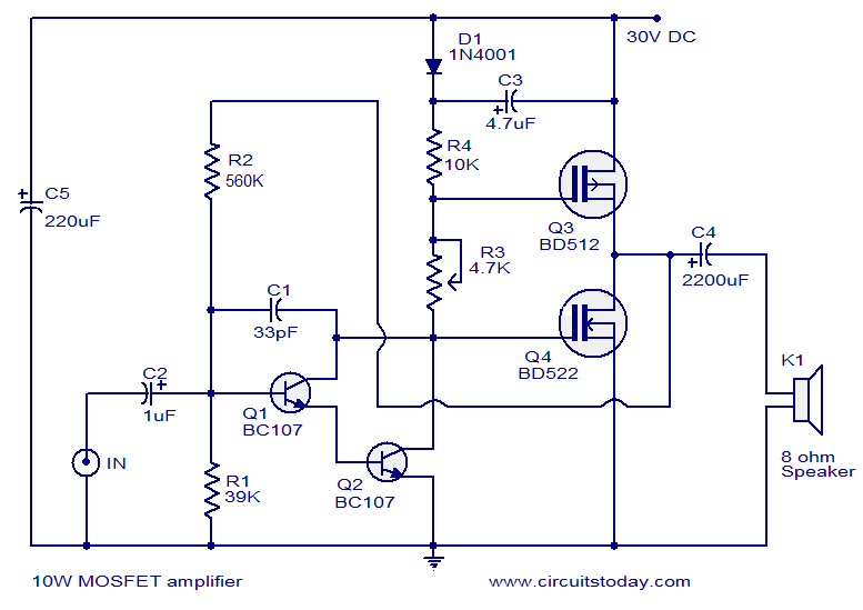
This article lists various types of audio amplifier circuits using MOSFETs. All circuits have been tested in a laboratory environment and have shown satisfactory performance. The amplifier utilizes one transistor, two MOSFETs, and a few resistors and capacitors in...
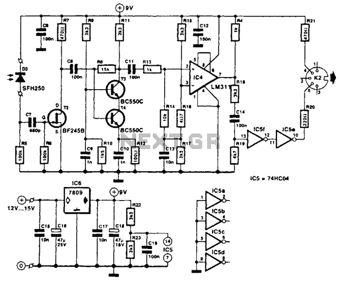
The receiver photodiode SFH250 is utilized to convert optical data pulses at a rate of 32.5 Kbps into electrical signals. The buffer T2 transmits these signals to a cascade amplifier consisting of transistors T3 and T4, followed by an...
The ZN414 integrated circuit (IC) contains a complete automatic gain controlled AM receiver within a compact three-pin package. With only a few external components, it is possible to construct a simple radio that offers excellent selection and reception capabilities....
This circuit controls a load, specifically a DC brushless fan, based on a temperature comparison with a setpoint. The transducer utilized is a diode in the forward bias configuration. When forward biased, the forward voltage drop across the diode...
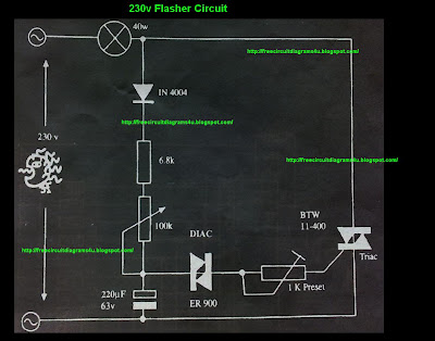
This circuit operates at 230V and can be utilized for party decoration purposes. It is sourced from an old circuit book titled "100 Circuit Book." The components include DIAC ER 900 and TRIAC BTW 11-400. The circuit is designed to...