
LED Interfacing with 8051

Interfacing LEDs with the 8051 microcontroller is a fundamental project that serves as an excellent introduction to microcontroller applications. The P89V51RD2 microcontroller, a member of the 8051 family, is particularly suited for this task due to its versatile I/O capabilities and ease of programming.
To begin, the circuit typically consists of the P89V51RD2 microcontroller connected to a series of LEDs through current-limiting resistors. Each LED is connected to a specific I/O pin of the microcontroller, allowing for individual control. The first step in the schematic design involves configuring the microcontroller pins as outputs. This can be achieved through the initialization of the appropriate registers in the microcontroller's firmware.
The circuit diagram will illustrate the connection of the microcontroller pins (for example, P0.0, P0.1, etc.) to the anodes of the LEDs, while the cathodes are connected to ground through resistors, typically in the range of 220 to 1k ohms, depending on the LED specifications and desired brightness. The choice of resistor value is crucial to ensure that the current flowing through the LEDs does not exceed their rated limits, thereby preventing damage.
The firmware should include a simple loop that turns the LEDs on and off in a sequence, which can be accomplished using delay functions to create a visually appealing effect. The source code provided may include functions for initializing the microcontroller, setting the port directions, and controlling the timing of the LED states.
In conclusion, this project not only demonstrates the basic principles of interfacing components with a microcontroller but also provides practical experience in programming and circuit design. The availability of source code and circuit diagrams facilitates a deeper understanding and enables users to replicate or modify the project for further experimentation.Learn how to interface LEDs with 8051 Microcontroller. Download free source code and circuit diagram of P89V51RD2 Microcontroller 🔗 External reference
Related Circuits
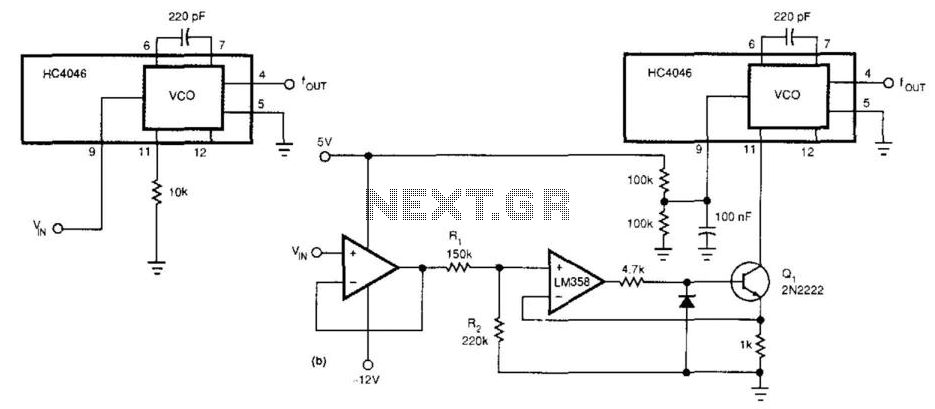
This circuit expands the linear frequency range of an HC4046 from one decade to nearly three decades. An LM358 is utilized as a constant-current sink, replacing the frequency-determining resistor (10 kΩ) connected from pin 9 to ground. For this...
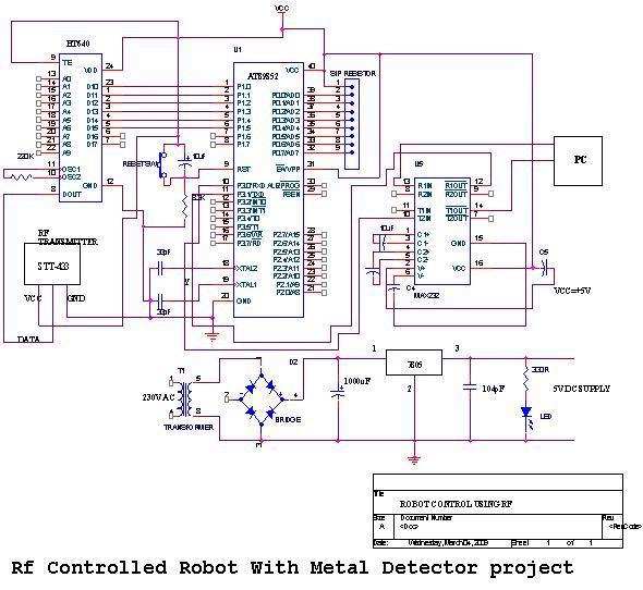
An embedded C-based RF-controlled robot equipped with a metal detector, along with wireless image and voice transmission capabilities. This project report is intended for electronics and communication engineering students. The project involves the design and implementation of an RF-controlled robot...
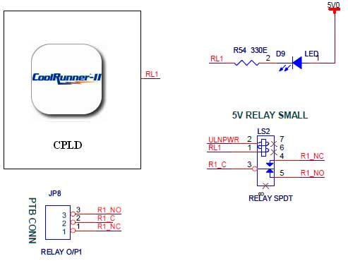
The CoolRunner-II board features external 5V relay interfacing, as indicated in the accompanying figure. The ULN2803 is utilized as a driver for the CPLD I/O lines, with the driver outputs connected to the relay modules. A PTB connector is...
This unique hat is a product of a procrastination project. During the study break for final exams, an invitation was received for a friend's hat-themed birthday party. With little else to occupy time (aside from studying), the decision was...
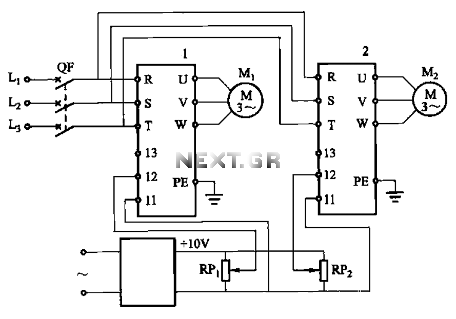
Adjust the potentiometers RPi and RPz to modify the speed of two motors. The circuit utilizes two potentiometers, designated as RPi and RPz, to control the speed of two separate motors. Each potentiometer is connected in a voltage divider configuration,...
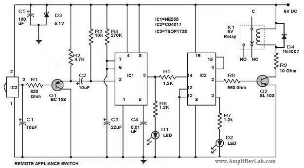
The circuit diagram of a remote-controlled appliance switch circuit includes two main components: IC1 (NE 555) and IC2 (CD 4017). The remote-controlled appliance switch circuit is designed to allow users to control electrical appliances wirelessly. The heart of this circuit...