relay interfacing with coolrunner ii cpld
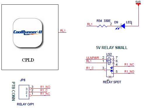
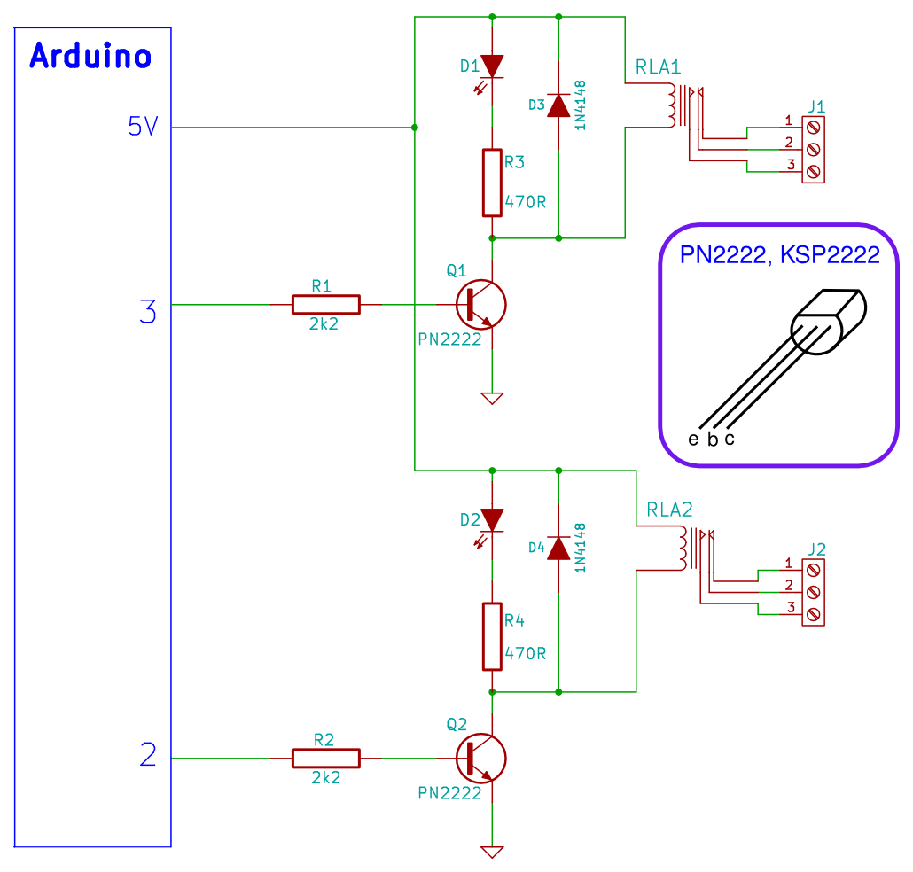
The CoolRunner-II board features external 5V relay interfacing, as indicated in the accompanying figure. The ULN2803 is utilized as a driver for the CPLD I/O lines, with the driver outputs connected to the relay modules. A PTB connector is provided for an external power supply if required.
The CoolRunner-II board is designed to facilitate the integration of external relay modules, allowing for the control of high-power devices through low-power CPLD I/O lines. The use of the ULN2803, a high-voltage, high-current Darlington transistor array, enables efficient switching of the relays. Each output of the ULN2803 can handle a significant amount of current, making it suitable for driving multiple relay coils simultaneously.
The external 5V relay interfacing is crucial for applications that require isolation between the control circuit and the load circuit. The relays can be activated by the CPLD outputs through the ULN2803, ensuring that the control logic remains safe from high voltages present in the load side. The PTB connector serves as an optional power supply input, allowing for flexibility in power management, especially in scenarios where the board's internal power supply may not suffice.
In terms of schematic design, the connections between the CPLD, ULN2803, and the relay modules should be clearly laid out. The CPLD I/O pins should connect to the inputs of the ULN2803, while the outputs of the ULN2803 should be linked to the relay coils. Additionally, each relay should have its own flyback diode connected in parallel to protect the driving circuit from voltage spikes generated when the relay coil is de-energized.
Overall, the CoolRunner-II board's design promotes efficient control of external devices while ensuring reliable operation and protection of sensitive components.The CoolRunner-ii board has external 5v Relay interfacing, indicated as in Figure. ULN2803 is used as a driver for CPLD I/O lines, drivers output connected to relay modules. PTB connector provided for external power supply if needed. 🔗 External reference

