
LED Light Show and Audio Amplifier all in one

The Picaxe 18M2 microcontroller is a versatile device that is well-suited for a variety of electronic projects. It is based on a PIC microcontroller architecture and offers a simple programming interface, allowing users to write code in a BASIC-like language. This ease of use makes it particularly appealing for hobbyists and educational purposes.
In this circuit, the Picaxe 18M2 is likely connected to various input and output components. Typical connections may include sensors, switches, and LEDs, which allow the microcontroller to interact with the physical environment. For instance, analog sensors can provide input data, which the microcontroller processes to control output devices such as motors or displays.
The circuit design may also incorporate a power supply circuit to ensure that the Picaxe 18M2 operates within its specified voltage range. This could involve the use of voltage regulators or battery management systems, depending on the application.
Programming the Picaxe 18M2 is accomplished through a dedicated programming interface, usually connected to a PC via USB or serial communication. The programming software allows for the uploading of code, debugging, and real-time monitoring of the microcontroller's performance.
Additional features of the Picaxe 18M2 include built-in support for various communication protocols, such as I2C and SPI, enabling it to interface with other microcontrollers and peripheral devices. This expands the potential applications of the circuit, allowing for complex interactions and data exchange between multiple components.
Overall, the integration of the Picaxe 18M2 in this circuit provides a robust foundation for developing programmable electronic systems, facilitating both simple and sophisticated projects.The hardware within this circuit involved a Picaxe 18M2 IC which is the programmable micro-controller in my design which can be programmed using a PC,.. 🔗 External reference
Related Circuits
This circuit is same as the above setup to drive 25 small Xmas lights. The lights operate at about 200mA and 3 volts. The supply voltage is set to 5 volts and the 4017 counter output will drop about...
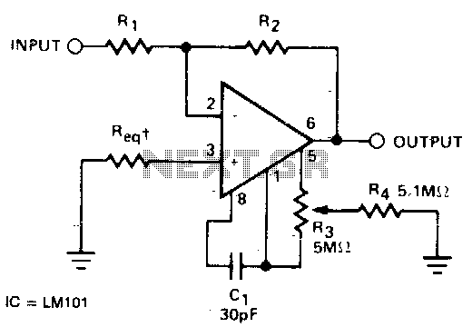
The required resistance (Req) may be zero or equal to the parallel combination of resistors R1 and R2 to achieve minimum offset. The circuit configuration described involves the use of two resistors, R1 and R2, connected in parallel. In a...

My circuit adds a transistor, to add feedback, and two resistors, to tailor the range of the control, with the result that a single-turn potentiometer gives a control range of about 2 to 30 microamps. I installed my circuit...
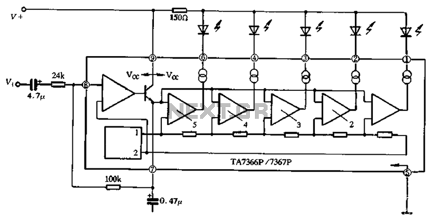
The TA 7366/7367 is a commonly used single display driver circuit manufactured by Toshiba Corporation. It features a 5 LED driver circuit and is designed in a 9-pin single in-line plastic structure. The circuit configuration includes an operational amplifier...
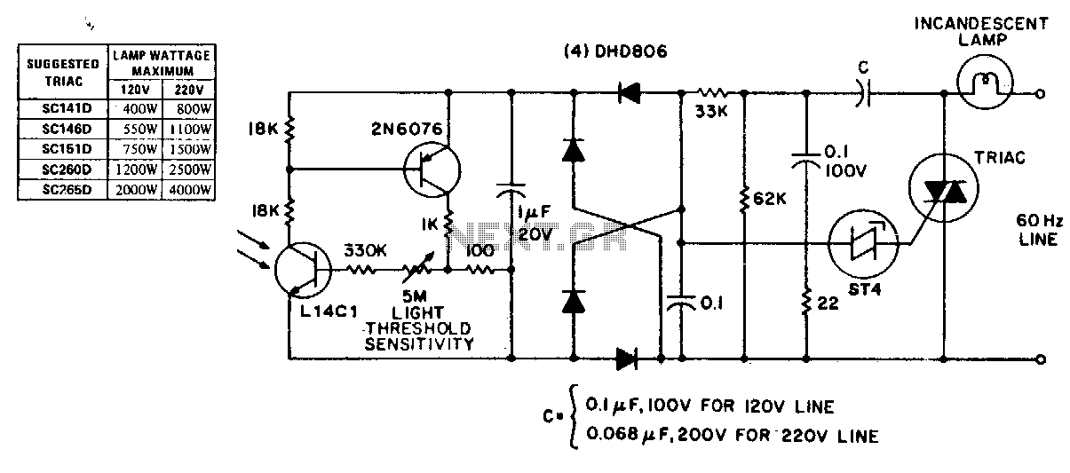
This circuit exhibits stable threshold characteristics based on the photo-diode current in the Ll4Cl, which generates a base-emitter voltage drop across the sensitivity setting resistor. The double phase shift network that supplies voltage to the ST-4 trigger ensures triac...
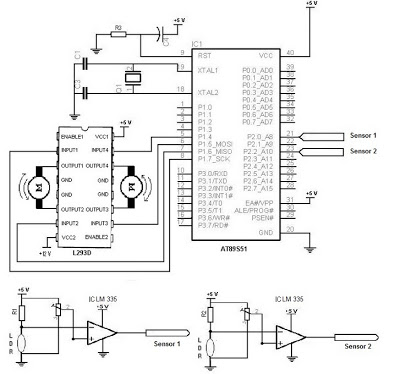
The electronic schematic of the Light Detector Robot can be divided into three main components: the sensor, the microcontroller, and the DC motor driver. The light sensor utilized in this design is a Light Dependent Resistor (LDR), which alters...