
LED Lighting For Consumer Unit Cupboard

The circuit described serves a critical function in ensuring safety and convenience in older residential electrical systems. The consumer unit, often located in a dimly lit area, can pose challenges during power outages, particularly when identifying electrical issues such as blown fuses or tripped breakers.
The system begins with the bell transformer, which converts the mains voltage to a lower voltage suitable for charging the NiCd batteries and powering the LED lights. The bridge rectifier (B1) converts the alternating current (AC) output of the transformer into direct current (DC), which is then smoothed by capacitor C1 to provide a stable voltage for the LEDs and charging circuit.
Charging of the NiCd batteries occurs continuously under normal operating conditions, with diode D1 preventing reverse current flow when the mains power is available. The charging current of approximately 7.5 mA, limited by resistor R2, ensures that the batteries remain topped up without overcharging.
In the event of a mains failure, capacitor C1 discharges through resistor R1, which acts as a timing element. The voltage across C1 decreases until it reaches a level that allows the battery voltage to turn on transistor T1. This transition is facilitated by resistors R3 and R1, which form a voltage divider that controls the base current of T1. When T1 is activated, it allows current to flow through diodes D4 and D5, illuminating the LEDs. The combined output of these high-current LEDs is designed to provide sufficient light to navigate the consumer unit area, enabling users to locate and address electrical issues safely.
Overall, this emergency lighting circuit is a practical solution for enhancing visibility in critical areas during power outages, thereby improving safety in residential electrical installations.The consumer unit (or electricity meter`) cupboard in some older houses is a badly lit place. If the bell transformer is also located in this cupboard, it may be used to provide emergency lighting by two high-current LEDs. These diodes are powered via a small circuit that switches over to four NiCd batteries when the mains fails.
The output voltag e of the bell transformer is rectified by bridge B1 and buffered by capacitor C1. The batteries are charged continuously with a current of about 7. 5 mA via diode D1 and resistor R2. The base of transistor T1 is high via R3, so that the transistor is cut off. When the mains voltage fails, C1 is discharged via R1; when the potential across it has dropped to a given value, the battery voltage switches on T1 via R3 and R1, provided switch S1 is closed. When T1 is on, a current of some 20 mA flows through diodes D4 and D5. The light from these LEDs is sufficient to enable the defect fuse or the tripped circuit breaker to be located.
🔗 External reference
Related Circuits

This circuit utilizes two quad voltage comparators, specifically the IC LM339, to illuminate a series of eight LEDs that indicate volume levels. Each of the eight comparators is biased at increasing voltages set by a voltage divider, allowing the...

The basic circuit illuminates up to ten LEDs in sequence, following the rhythm of music or speech picked up by a small microphone. The expanded version can drive up to ten strips, formed by up to five LEDs each,...
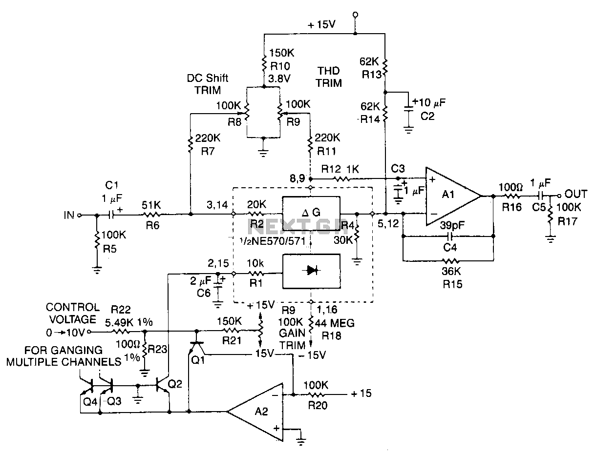
This typical circuit utilizes an external operational amplifier for improved performance, along with an exponential converter to achieve a control characteristic of -6 dB per volt. Trim networks are incorporated to eliminate distortion and offset, as well as to...
Typical segment display LEDs consume around 25 mA for each segment and should be limited to this current with resistors. For a six-digit display to be current limited, at least 42 series resistors are needed. The brightness of the...

A CD4511B CMOS LED display driver can be utilized to operate a common cathode LED display. Current limiting resistors are employed to restrict the segment current to the specified value at the maximum supply voltage. The CD4511B is a...
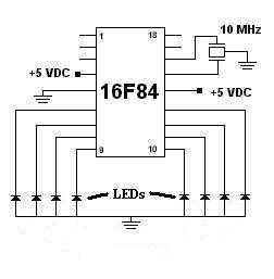
This was my first successful project with a PIC chip. I used a 16F84 with a 10MHz resonator with built-in caps. Click here to view the source code to this project. The code is written in Hi-Tech C. Click...