
LED dimmer circuit

The design of a six-digit segment display circuit requires careful consideration of current limiting and brightness control to ensure optimal performance and longevity of the LEDs. Each LED segment draws approximately 25 mA, necessitating the use of resistors to limit the current flowing through each segment. In a configuration where all segments are illuminated, a total of 42 series resistors are required to maintain the current within safe operating limits.
The output voltage of the regulator circuit is adjustable, ranging from 0 to 4.3 volts, which directly influences the brightness of the LEDs. This variability allows for customization of the display brightness based on user preference or environmental conditions. Potentiometer P1 serves as a coarse adjustment for the output voltage, while P2 allows for finer tuning, facilitating precise control over the LED brightness.
It is crucial to ensure that the total current drawn by the display does not exceed 1 ampere. For instance, with seven segments illuminated, the current can reach approximately 1050 mA (7 segments x 25 mA), which surpasses the maximum allowable current. This necessitates the use of a suitable heatsink for transistor T1, as the elevated current levels will generate considerable heat that must be dissipated to prevent thermal damage to the component.
In summary, the circuit design for a six-digit segment display involves current limiting via series resistors, adjustable output voltage for brightness control, and adequate thermal management for high current scenarios. Proper implementation of these elements will ensure reliable operation and longevity of the LED display.Typical segment displays LEDs consume around 25 mA for each segment and should be limited to it with resistors. If a six digit display is to be current limited, at least 42 series resistors are needed. The brightness of the LEDs are dependent on the output voltage. Since the voltage regulator is variable, the brightness of the LEDs is also variabl e. Potentiometer P1 is used for rough adjustment while P2 is used to trim the brightness in finer resolution. The output of the regulator circuit can be varied from 0 to 4. 3 volts. Before tuning the circuit, set the pot to zero point, then slowly adjust the pots until the desired brightness is achieved.
In a typical six segment disply, the maximum current must not exceed 1 ampere. For example: if one segment consumes 25 mA each, then 7 segments of a six digit display will consume around 1050 mA. That is a bit more than 1 ampere! The transistor T1 must be heatsinked because high current consumption will produce a lot of dissipated heat.
We aim to transmit more information by carrying articles. Please send us an E-mail to wanghuali@hqew. net within 15 days if we are involved in the problems of article content, copyright or other problems. We will delete it soon. 🔗 External reference
Related Circuits
T1 and T2 in the circuit form the inherent oscillator, while T3 serves as the output stage. The network consists of a high-pass filter (C3, C4, R6, and R7) and a low-pass filter. The output from this network is...

The following circuit is a power amplifier circuit for an FM transmitter with an output power of 30 watts. The power amplifier circuit utilizes a power transistor of type 2SC1946A. The FM transmitter operates with a 13.8-volt DC power...
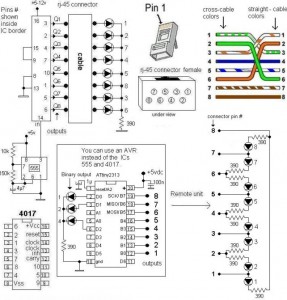
A LAN tester circuit diagram is presented in two designs. The first design utilizes a timer IC 555 and a decade counter 4017. The second design employs a microcontroller ATtiny2313. The first design of the LAN tester circuit incorporates the...
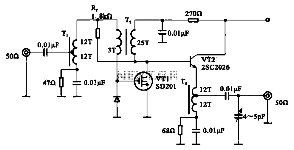
A broadband amplifier circuit utilizing a negative feedback amplifier configuration is presented. This circuit employs transformer coupling and a combination of amplifying sections and field-effect transistors (FETs). The input signal is applied to the center tap of the transformer...
Figure 1 consists of a Programmable Unijunction Transistor (PUT) and an automatic interval timer circuit. In this circuit, the PUT serves as the oscillator. The switch S1 is used to toggle between interval timing and automatic timing modes. When...
This page is browser-friendly. To enhance readability, adjust your browser window to be narrower than the full screen. The page consists of two parts: the first part features a basic program demonstrating the RFID reader's functionality, while the second...