
LED lights inside the refrigerator circuit diagram

The LED lighting circuit schematic for the refrigerator is designed to efficiently illuminate the interior while maintaining low power consumption and minimal heat output. The arrangement of the eight high-brightness white LEDs in a transparent plastic tube allows for even light distribution throughout the refrigerator's interior. The use of a power transformer ensures that the circuit operates safely at lower voltages, reducing the risk of electrical hazards.
The full-wave rectification process, facilitated by the diodes (VD1 and VD2), converts the alternating current (AC) into direct current (DC), which is essential for the operation of the LEDs. The filtering capacitor (C1) smooths out any ripples in the DC output, while the resistor (R1) helps to limit the current flowing through the circuit, protecting the LEDs from potential damage due to overcurrent conditions.
The zener diode (ZD1) plays a crucial role in voltage regulation, ensuring that the output remains stable at 12V regardless of variations in the input voltage. This stability is vital for maintaining consistent brightness levels of the LEDs over time.
The configuration of the LEDs, with each having a forward voltage of 3.1V, allows for a series connection that maximizes the efficiency of the power supply. With a total power consumption of less than 1W, the circuit is designed to provide adequate illumination—approximately 40 lumens—while remaining energy-efficient. The minimal heat generation is an added advantage, contributing to the longevity of the LED components.
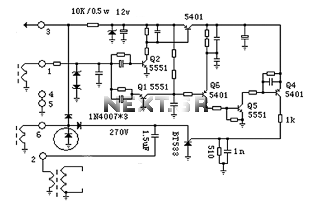
The door control switch (SB) is an essential feature that activates the LED lighting when the refrigerator door is opened, enhancing user convenience. The design of this circuit not only meets the functional requirements of refrigerator lighting but also adheres to energy efficiency standards, making it a suitable choice for modern appliances. As shown in the refrigerator for the LED lighting circuit schematic. The circuit is composed of eight LED lights white LED high-brightness light-emitting tube. LED are mounted in a white transparent plastic pipe, plastic pipe length equal to the height of the refrigerator cabinet. AC power via the door switch SB and fuse FU in the power transformer TR secondary to Double 6V AC voltage is full-wave rectified by the diode VD1, VD2, limiting filtering capacitor C1, the resistor R1, the zener diode ZD1 smooth DC stable 12V power supply to the LED light bar.
White LED forward voltage single 3.1 V, 12V supply, each LED power 0.06 W, 4 only 0.25W, a total of two groups, the total power consumption of less than 1W. Thus, LED total luminous intensity can be close to 40 lm, only a weak heat and consume very little power.
SB is the refrigerator door control switch, when the switch lighting the refrigerator LED, SB connection have to be changed then.
Related Circuits
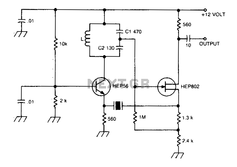
A typical Butler oscillator operating within the frequency range of 20 to 100 MHz incorporates a Field Effect Transistor (FET) in the second stage of its configuration. The circuit exhibits reliability issues when utilizing two bipolar transistors. In some...
The anatomy of two ignition experiments revealed a common issue, specifically that both ends of the ignition coil are equipped with a diode. This design choice by manufacturers has implications for performance. The ignition coil generates a negative half-cycle...
A JFET-bipolar cascode circuit is designed to deliver complete video output for driving the cathode of a CRT. The configuration offers an approximate gain of 90. The cascode arrangement mitigates issues related to the Miller capacitance of the JFET...

The circuit operates from a 5-V supply and has a current consumption of 2 mA. The output functions as a current source that can drive or suppress a current exceeding 75 mA with a voltage swing of 4.5 V....
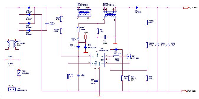
This article outlines a proposed solution for a 200 W power supply utilizing the FSFR2100 Fairchild Power Switch (FPS). The input voltage range is 90 to 265 VRMS, and it features six outputs. The 200 W power supply circuit based...

In this amplifier circuit, the gate of the MPF 102 is biased with an external voltage. This circuit achieves tighter control of the operating point and biasing conditions. The amplifier circuit utilizing the MPF 102 field-effect transistor (FET) is designed...