
Fet Amplifier With Offset Gate Bias Circuit

The amplifier circuit utilizing the MPF 102 field-effect transistor (FET) is designed to enhance the stability and performance of the amplification process. The MPF 102, known for its low noise characteristics and high input impedance, is particularly suitable for applications requiring precise signal amplification.
In this configuration, the gate of the MPF 102 is connected to an external voltage source, which serves to set the bias point of the transistor. This external biasing allows for improved control over the operating point, ensuring that the transistor remains in the desired region of operation, typically the saturation region for amplification purposes. The use of an external voltage rather than relying solely on the inherent characteristics of the transistor helps mitigate variations that may arise due to temperature changes or component tolerances.
The circuit may include additional components such as resistors and capacitors to form a biasing network, which further refines the operating conditions. Resistors connected to the gate can help stabilize the bias point by providing a defined path for the gate current, while capacitors can be employed for coupling and decoupling purposes, ensuring that AC signals are amplified effectively without distortion.
Overall, this amplifier circuit configuration is beneficial for applications that demand high fidelity and low distortion in signal processing, making it suitable for audio amplification, sensor signal conditioning, and communication systems. The precise control of the operating point achieved through external voltage biasing contributes significantly to the reliability and performance of the amplification circuitry. In this amplifier circuit, the gate of the MPF 102 is biased with an external voltage. This circuit achieves tighter control of the operating point and biasing conditions.
Related Circuits
This is a simple game show timer designed for beginners. The power source can be a standard 12-volt lantern battery or a battery pack made from C or D cells. The lamps used can be regular flashlight bulbs; the...
The chip in the center with small bullet holes is likely proprietary. It is possible to salvage a few components from it, although understanding the circuit is not necessary for this purpose. Additionally, it is confirmed that the device...
It is based on an LM2917 and an SCR, which has the advantageous characteristic of preventing mis-timed sparks, a highly desirable feature for high-output rotary engines. When the engine reaches the rev limit during acceleration, the transition is smooth...
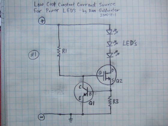
Here is a simple and cost-effective Power LED driver circuit. This power LED driver circuit is designed to efficiently drive high-power LEDs with a stable output. The circuit typically consists of a few key components: a power supply, a current...
Locker Guard Circuit Diagram. This compact circuit is designed to protect a locker or almirah from burglary. If the locker is opened while in the armed state, the circuit triggers a loud police siren to deter the burglary attempt. The...
The P5 design utilizes eight 74HC/AC240 chips, which function as octal inverting buffers. Each 74HC/AC240 chip contains two groups of four inverters, each managed by a tri-state enable pin (pins 1 and 19). The 74AC240 chips (U1-U5) serve as...