
Pathway Lighting with LEDs

The described circuit involves a solar-powered pathway lighting system designed to illuminate walkways during nighttime. This system utilizes solar panels to harness sunlight during the day, converting it into electrical energy stored in a rechargeable battery.
The pathway lighting comprises several key components, including solar panels, a rechargeable battery, a bifilar wound toroidal inductor, a light-emitting diode (LED) array, and a control circuit. The solar panels are typically mounted in a position that maximizes sun exposure, ensuring efficient energy collection.
The bifilar wound toroidal inductor serves multiple purposes in the circuit. It can be used for energy storage, smoothing out the voltage supplied to the LED array, and reducing electromagnetic interference. The bifilar winding technique enhances the inductor's efficiency, allowing for better performance in energy management.
The control circuit is responsible for regulating the flow of electricity from the battery to the LED array. It includes a light sensor that detects ambient light levels, automatically switching the LEDs on at dusk and off at dawn. This feature ensures that the pathway is illuminated only when necessary, conserving battery life.
The LED array provides bright, efficient illumination, utilizing minimal power while offering a long lifespan. The arrangement of LEDs can be designed to achieve uniform light distribution along the pathway, enhancing visibility and safety for pedestrians.
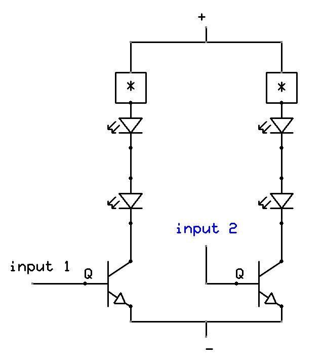
Overall, this solar-powered pathway lighting system is an eco-friendly solution for outdoor illumination, combining renewable energy technology with efficient lighting design.Simple pathway lighting that would provide illumination for the path at night. Extension for the Solar garden Light. The torroid is bifilar wound. The Torr. 🔗 External reference
Related Circuits
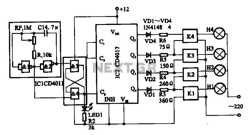
This circuit illustrates a circular lighting control system. It consists of four two-input NAND gates from the CD4011 series, which form a non-inverting multivibrator. This multivibrator generates a pulse that is used to shape the output of an RS...
This is a straightforward project suitable for individuals with basic electronic skills. Connecting this circuit to an audio source will cause the LEDs to blink in sync with the rhythm. The described project is an audio-activated LED circuit that visually...
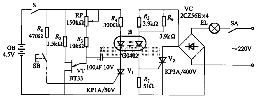
The circuit illustrated in Figure 2-48 consists of two configurations. Configuration 2-48 (a) operates using a 4.5V battery, while configuration 2-48 (b) employs AC capacitors to reduce the voltage supply. In configuration 2-48 (a), the delay time is influenced...

A simple half-wave rectifier capacitor step-down regulator circuit composed of VD1, VD2, C1, and C2 generates a DC voltage of approximately 12V after power is supplied across capacitor C2. The transistors VT1-VT3 are configured for delay circuits. This DC...
In this electronic roulette wheel, the 555 timer functions as a pulse generator with a fading frequency. The 4017 counter activates LEDs sequentially in the selected string, while a D-type flip-flop (4013 IC) serves as a divider by two...

The circuit utilizes a 555 timer IC to create a lighting group delay effect, as illustrated in Figure 2-46. It consists of the 555 IC along with a resistor and capacitor configuration that establishes the delay. The circuit remains...