
LED voltmeter schematic needed

The proposed LED voltmeter circuit utilizes a series of light-emitting diodes (LEDs) to visually represent the voltage level of a variable power supply. This circuit can be designed using a voltage divider, an operational amplifier, and a set of LEDs calibrated to indicate specific voltage ranges.
To begin, a voltage divider composed of two resistors (R1 and R2) is connected across the variable power supply. The output voltage from the voltage divider is proportional to the input voltage and can be calculated using the formula Vout = Vin * (R2 / (R1 + R2)). This output voltage is then fed into the non-inverting input of an operational amplifier (Op-Amp), which is configured for voltage comparison.
The Op-Amp is set up with a reference voltage that corresponds to specific voltage thresholds. For instance, if monitoring a supply voltage ranging from 0 to 12 volts, the Op-Amp can be configured to switch states at intervals such as 2V, 4V, 6V, 8V, 10V, and 12V. Each output from the Op-Amp can control a corresponding LED. When the voltage exceeds a certain threshold, the Op-Amp output will go high, turning on the associated LED.
To enhance the circuit's functionality, a resistor can be placed in series with each LED to limit the current and prevent damage. Additionally, a potentiometer can be included in the voltage divider to allow for calibration of the circuit, ensuring accurate voltage readings.
The final output will be a series of lit LEDs, each representing a specific voltage level, providing a clear and immediate visual indication of the variable supply's voltage. This LED voltmeter circuit is not only simple to construct but also effective for real-time voltage monitoring in various applications.Hello, I need a simple to make LED based (not 7-segment) voltmeter to monitor the voltage of a variable supply. I have found this circuit.. 🔗 External reference
Related Circuits
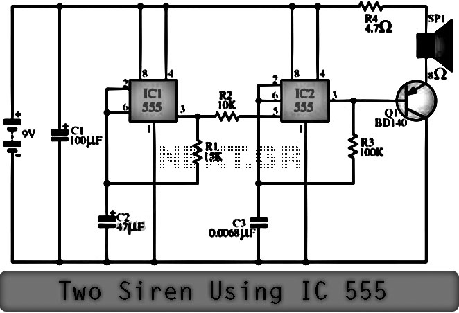
The function of the Two Siren Sound Circuit utilizing IC 555 is divided into three parts: low frequency production, manufacturing of a shrill frequency, and low frequency output. The low frequency is generated by IC1, which is connected to...

An embedded C-based RF-controlled robot equipped with a metal detector, along with wireless image and voice transmission capabilities. This project report is intended for electronics and communication engineering students. The project involves the design and implementation of an RF-controlled robot...
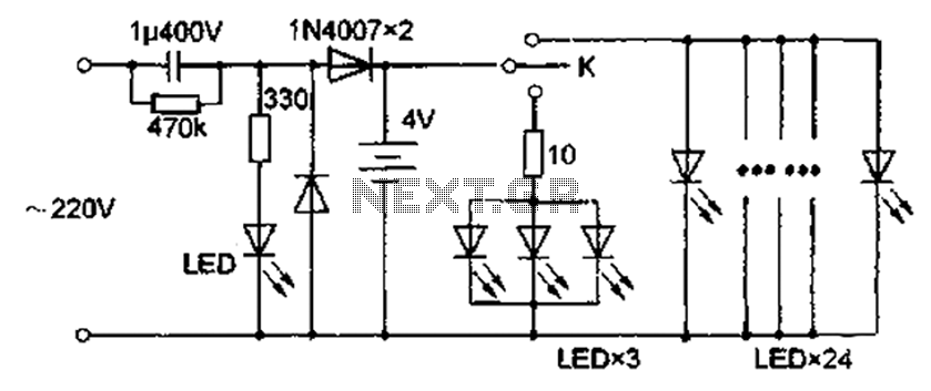
The circuit diagram depicted in Figure 5 illustrates a system for charging a lead-acid battery using 220V AC power. The circuit employs a capacitor, buck converter, and diode rectifier for this purpose. A red LED indicates the charging status....
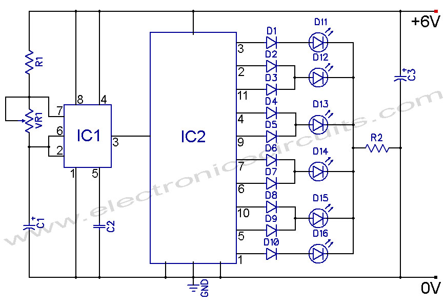
4017 LED Knight Rider Running Light Circuit Diagram. In this 4017 Knight Rider circuit, the 555 timer is configured as an oscillator. It can be adjusted to produce a variety of timing intervals. The 4017 LED Knight Rider circuit utilizes...
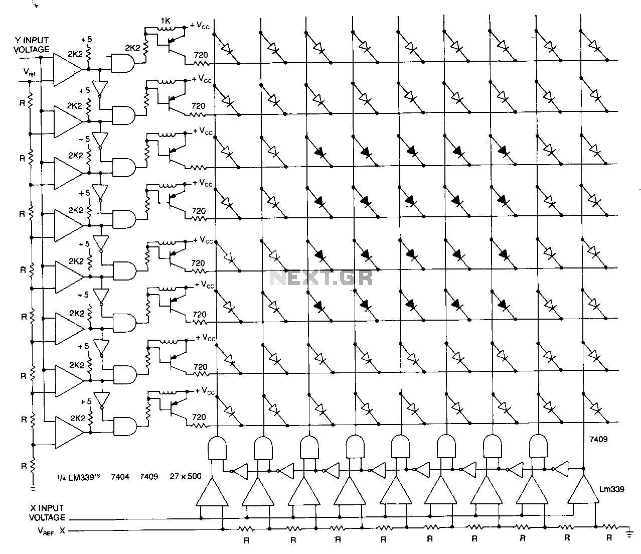
This matrix can display the values of two variables, such as frequency and voltage. The display consists of a graph made from a matrix of LEDs. The LEDs on each axis are color-coded: red indicates out of tolerance, while...
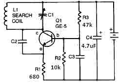
This metal detector circuit requires a power supply of 9 volts (DC) or a 9-volt battery. The circuit includes a variable capacitor C1 valued at 365 pF, a 100 pF silver mica capacitor C2, a 0.05 µF disc capacitor...