
Small Metal detector schematic circuit

The metal detector circuit operates by generating an electromagnetic field through the use of capacitors and transistors, which are essential components for signal processing. The variable capacitor C1 allows for tuning the circuit to different frequencies, optimizing the detection capability based on the metal's properties being searched. The use of a 365 pF variable capacitor is crucial as it can be adjusted to change the resonant frequency of the circuit, thus enhancing sensitivity to specific types of metals.
Capacitor C2, a 100 pF silver mica capacitor, is known for its stability and low loss characteristics, making it suitable for RF applications. This capacitor plays a significant role in maintaining the integrity of the signal being processed. Capacitor C3, with a value of 0.05 µF, serves to filter high-frequency noise, ensuring that the output remains clear and reliable. Meanwhile, capacitor C4, rated at 4.7 µF, may be used for coupling or bypassing applications, aiding in the stabilization of the power supply voltage across the circuit.
The transistor Q1, which can be an RCA SK3011 or an equivalent NPN transistor, acts as a switching or amplifying device. Its role is to control the current flow through the circuit, allowing for the detection of metal objects by amplifying the signal generated by the electromagnetic field. The choice of an NPN transistor is critical, as it provides the necessary gain and switching capabilities required for efficient operation.
The resistors in the circuit, while not specified in detail, are integral to setting the biasing conditions for the transistor, controlling current flow, and ensuring stable operation of the metal detector. Proper selection and configuration of these resistors are essential for achieving optimal performance and sensitivity in detecting metallic objects.
Overall, this metal detector circuit design emphasizes the importance of component selection and configuration, ensuring reliable operation and effective metal detection capabilities.This metal detector circuit needs to be powered using a 9 volts power supply ( DC) or a 9 volts battery. The C1 capacitor is a variable capacitor with a value of 365 pF, C2 is a 100pF silver mica capacitor, C3 is a 0.05 uF disc capacitor and the C4 is a 4.7 uF capacitor.
The Q1 transistor can be RCA SK3011 npn transistor or equivalent type and all resist.. 🔗 External reference
Related Circuits
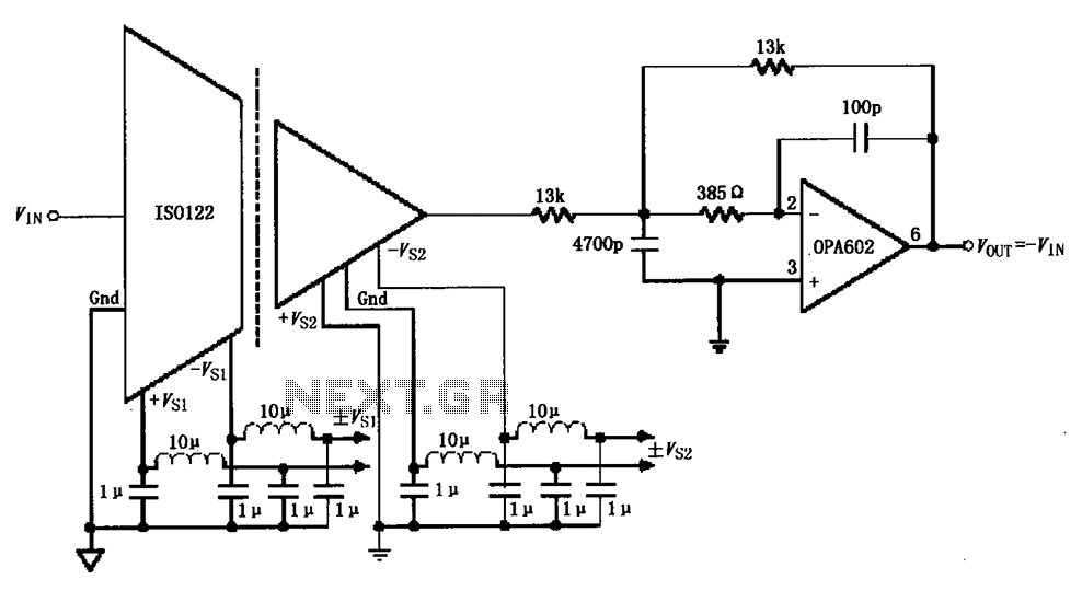
The ISO122/124-type filter circuit is designed to address noise suppression from the DC/DC converter. The internal oscillator frequency of the ISO122/124 modem is set to 500 kHz. The circuit employs inductors and capacitors for filtering to mitigate any beat...
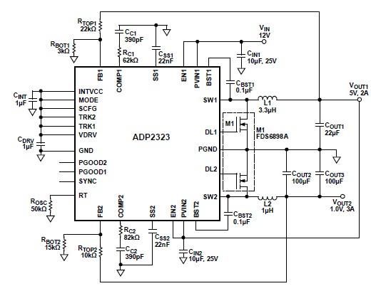
The ADP2323 DC-DC converter is designed to deliver two output voltages with specified maximum output currents. The first channel provides a 5-volt output with a maximum current of 2 Amperes, while the second channel supplies 1 volt with a...
This circuit functions as an RF power amplifier designed to operate with a power supply capable of delivering 13 volts at a current of 10 amperes. Careful assembly of the power source is essential. It utilizes a shielded transformer...
555 timer circuits LM555 - Astable Oscillator Calculator, Capacitor Calculator, Basic Circuits for the LM555 Timer, Triggering and Timing Helpers for Monostable Timers, Controlling Circuits for LM555 Timers, Advanced Circuits for the LM555 Timer, LM556 Timers with Complementary or...
Full sine wave UPS information in English, along with detailed C language source code. English proficiency may be a concern, so caution is advised. A full sine wave Uninterruptible Power Supply (UPS) is designed to provide a stable and continuous...
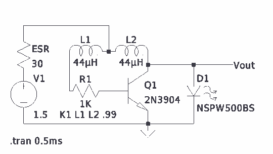
There is much pleasure in useless knowledge. The value of the inductors (44 µH) was determined using an online toroid calculator, specifying an FT-50-43 toroid with 10 turns through it. The described circuit involves the use of an FT-50-43 toroidal...