
LED3X Solar Tracker Assembly

The LED3X series Tracker PC board is designed for efficient assembly and reliability. The use of through-hole components simplifies the assembly process, allowing for easier handling and soldering. To maximize the integrity of the circuit, it is essential to follow a systematic assembly procedure. This includes ensuring that components are inserted correctly and that the soldering process is conducted in a way that mitigates the risk of damage from heat or static discharge.
The board design incorporates features that facilitate easier troubleshooting and maintenance. The clear labeling of component positions and the inclusion of test points allows for efficient verification of circuit functionality. The use of a grounded workbench and wrist straps is paramount in preventing static discharge, which can lead to component failure.
The emphasis on the Ohmmeter test highlights the importance of verifying circuit integrity before powering the device. This proactive approach to testing ensures that any issues are addressed prior to operation, reducing the risk of component damage during initial use.
Furthermore, the outlined substitutions of parts emphasize adaptability in design, allowing for enhancements in reliability without compromising performance. The flexibility in component values, particularly for the capacitors, provides options for optimization based on available resources while maintaining circuit functionality.
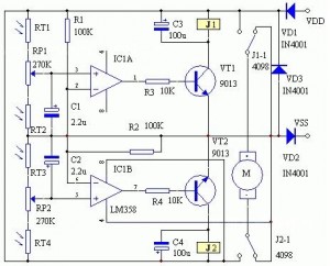
In summary, the LED3X series Tracker PC board represents a well-thought-out design that balances ease of assembly, reliability, and adaptability, making it suitable for various applications while ensuring robust performance.The above table is useful to determine the capabilities of the MOSFETs for the various versions. However, the connectors I have used on the LED3X "c" series is not rated for such high currents on a continuous basis. The connector is technically rated for 7 amps continuous. I find that 10 amps is not to excessive if done intermittently and much hig her currents if the the pulses are short. An experiment I have done was to drive a 12V automotive door window motor. This motor draws about 4 amps at 13. 8V. I raised the voltage to 44V with a pulse width of about 1 second out of a cycle time of 18 seconds. The peak current into the motor is 55 amps @ 1/2 second! Everything remained reasonably cool. Cool huh! The LED3X series Tracker PC boards uses through hole parts. These components are easier to assemble than the surface mount parts on the previous LED3 tracker. The assembly should be done in the specific order outlined to minimize the risk of damage to the circuits in case there are solder shorts or misplaced components. The components in this circuit are susceptible to damage through static discharges. Use normal static discharge prevention techniques such as a grounded workbench, soldering iron, and personal grounding wrist straps.
Also the large mounting hole is connected to the negative power terminal and should be the first point touched when handling the circuit until the connector is installed which can then be the first thing touched. When I say to "Tack Solder" this means to solder one lead of a component on the top side of the board.
I have arranged all the components so one easily accusable lead is always on the end closest to the mounting hole. The components are small and light and one can`t turn the board over unless tack soldered because they will fall out.
Lay the board flat on a table and insert the components so the leads are flush with the table. This make for a clean flat back side. I assemble and tack solder all small components on the top side before turning over to complete the soldering. Also! There have been some substitutions of parts throughout the circuit. These were done mainly due to parts availability. OK, to be honest, I got some good deals on parts at ebay. I will comment about substitutions throughout the assembly instructions. These substitutions generally improve the circuit reliability. The most important test to perform is the Ohmmeter test. This board is laid out in such a way that almost all circuit traces can`t short out to each other, rather, these shorts will be to ground.
Shorts can be caused by a variety of things. The most common is a solder bridge but shorts could come from the PC board manufacturer also. The Ohmmeter test is easy to do. Just set the Ohmmeter to something like 20K Ohms with the - terminal connected to the ground plane. The + lead then tests all the circuit pins looking for zero ohms or shorts. Don`t worry if a higher value is read as this is most likely just the forward drop of the circuit junctions. You can prove this by changing the Ohmmeter scale. If it is a junction the resistance value read will change. If it is a true resistance the value will be the same. Step 12. Install Q6 KSC2330YBU or 2SD667-D NPN Transistor and solder. A BC337 or 2N3904 can be used for 24V operation. Note!, the different package orientations. The BC337 or 2N3904 needs to be installed with the Collector and Base leads reversed. ("c3 revision" has the leads correct for the KSC2330YBU and 2SD667-D. ) C2 47uF 50V Electrolytic Capacitor. Observe the polarity. The stripe is Minus. Was 1uF in the diagram. (Actually this capacitor is quite non critical and may be 22uF and with other voltages, 16V or higher.
) C1 47uF 50V Electrolytic Capacitor. Observe the polarity. The stripe is Minus. Was 1uF in the diagram. (Actually this capacitor is quite non critical and may be 22uF and with other voltages, 16V or higher. ) Vin volts on CONN1 pi 🔗 External reference
Related Circuits
Wibowa Chou from IR discusses the benefits of fourth-generation IGBTs compared to MOSFETs, particularly in the context of a practical solar inverter application. Fourth-generation Insulated Gate Bipolar Transistors (IGBTs) offer significant advantages over Metal-Oxide-Semiconductor Field-Effect Transistors (MOSFETs) in various applications,...
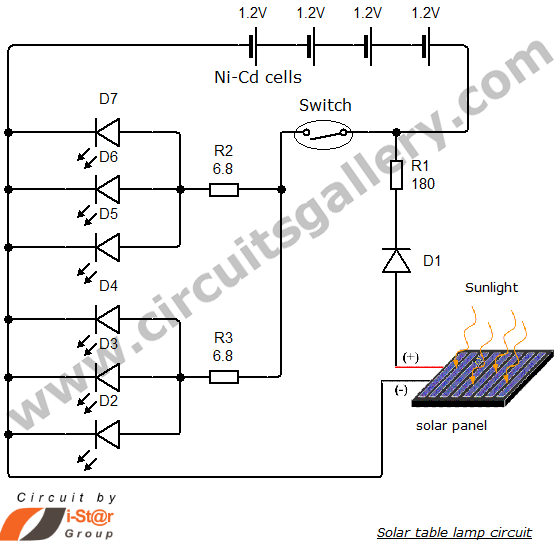
Solar energy has become a popular alternative for electricity production. This project focuses on teaching school students how to create solar lamps for their homes. The primary components of this simple solar lamp circuit include a small solar panel...
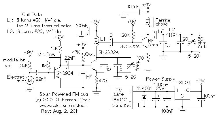
Numerous miniature FM transmitter bug circuits are available online; however, this particular design is distinctive as it operates entirely on solar power, eliminating the need for a battery. The transmitter will function as long as sunlight is incident on...
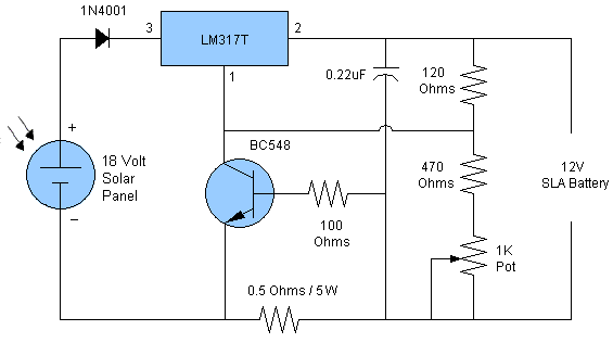
Solar battery charger schematic and description. This solar battery charger circuit is capable of charging a 12V lead-acid battery or sealed lead-acid (SLA) battery. The solar battery charger circuit is designed to convert solar energy into electrical energy for charging...
Solar PV Modules: UL Listed and installed worldwide, these solar panels are reliable, with an excellent performance record in the field. One does not need to be a mechanic or possess mechanical skills to create solar module panels. Prices...
The circuit consists of two stages. The first stage is a switch or cut-off device. It detects a voltage above 0.7V from the solar panel, and the resistance between its collector-emitter terminals reduces to a very small value. The...