
Levitation PWM

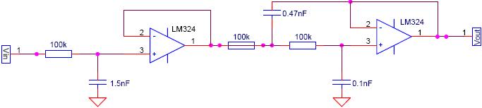
The PWM circuit described operates by modulating the width of the pulses to control the power delivered to a load. The core components include the oscillator, which generates a sawtooth waveform, and the driver stage that interfaces with the switching element, typically a transistor or MOSFET. The sawtooth waveform is essential for creating a variable duty cycle, which effectively controls the average voltage and current supplied to the load.
In this configuration, capacitor C1 plays a critical role in timing the discharge cycle, which influences the frequency of the PWM signal. The diodes D1 and D2 are strategically placed to manage the current flow, ensuring that the feedback mechanism operates correctly. Resistor R6 limits the current through D1, thus preventing excessive voltage drop and ensuring that the circuit remains stable during operation. Meanwhile, resistor R2 limits the current through D2, allowing for a higher current flow that is necessary for the desired operation of the circuit.
The feedback system is crucial for maintaining the oscillator's function. By ensuring that the negative input is consistently below the positive input, the circuit can reset effectively, thereby maintaining continuous operation. The choice of a sawtooth waveform, while not as ideal as a triangular waveform in some applications, generally suffices due to the robustness of the PWM technique in a variety of electronic applications. The simplicity of the design, requiring fewer components, contributes to cost-effectiveness and ease of implementation in various electronic systems.The switched controller that I used is nice, but a PWM (pulse width modulation) circuit is better. It provides cool-running operation and linear operation. It can be implemented with a small number of components. When C1 is sufficiently discharged the current through D1 is limited by R6 whilst the current through D2 is limited by R2, so will be 10 times as high as that through D1. Because of this current ratio, it can be guaranteed that there will be less voltage dropped across D1 than across D2, so the negative input will always fall below the positive input and the oscillator will always reset. To offset these advantages, the oscillator gives a sawtooth rather than a triangular waveform but there are very few occasions when this has any practical significance.
🔗 External reference
Related Circuits
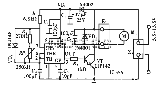
The circuit operates using pulse position modulation, which is a method distinct from the more commonly utilized pulse width modulation for speed control. A 555 timer is employed as a square wave modulator, generating output pulses with a fixed...
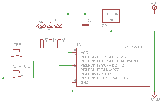
This project demonstrates the use of an ATTiny microcontroller and an RGB LED to create a light that continuously cycles through random colors, with the ability to change color dramatically at the press of a switch. The inspiration for...
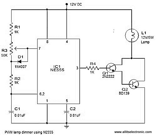
A simple and efficient PWM lamp dimmer utilizing the timer IC NE555 is presented in this article. Traditional linear regulator-based dimmers achieve a maximum efficiency of only 50%, which is significantly lower than PWM-based dimmers that can exceed 90%...
The HCS12 series of microcontrollers does not include dedicated internal digital-to-analog conversion hardware. Therefore, external hardware, such as a digital-to-analog conversion integrated circuit (IC), is required. To implement digital-to-analog conversion (DAC) in systems utilizing the HCS12 microcontroller, an external DAC...
PWM waveforms are frequently employed to regulate the speed of DC motors. The mark/space ratio of the digital waveform can be established either by utilizing an adjustable analog voltage level (as seen in a NE555-based PWM generator) or through...
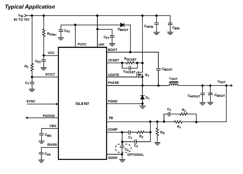
The ISL8107 is a single-phase, non-synchronous buck controller equipped with an integrated high-side MOSFET driver. It operates within an input voltage range of 9V to 75V. The internal reference voltage is 1.192V with a tolerance of ±1% across the...