
Light-Activated Alarm With Latch Circuit

This circuit operates primarily as a light-sensitive alarm system, utilizing a combination of resistors, transistors, and a silicon-controlled rectifier (SCR) to achieve its functionality. The light detection is facilitated by R5, which, upon exposure to light, allows current to flow through it. This current flow results in the forward biasing of transistor Q1, enabling it to conduct.
The sensitivity of the circuit is adjustable through R6, which can be varied to control the threshold at which the alarm is activated. This adjustment allows the system to be tailored for different lighting conditions or specific applications where light detection is required.
Once Q1 is activated, it provides the necessary emitter voltage to trigger SCR1. The SCR, a semiconductor device capable of controlling high power, remains latched once triggered, allowing current to flow to the alarm bell or buzzer (referred to as LQ1). This action results in the sounding of the alarm, alerting users to the presence of light.
To reset the alarm, a momentary press of switch S1 is required. This action interrupts the current flowing through SCR1, effectively unlatching it and silencing the alarm. It is crucial to implement a self-interrupting alarm mechanism, such as an electromechanical buzzer or bell, to ensure that the alarm can operate independently without additional manual intervention after it is triggered.
Overall, this circuit serves as an effective light-detection alarm system, combining simplicity with functionality, making it suitable for various applications where light monitoring is essential. In this circuit, light causes R5 to conduct forward-biasing Ql. R6 sets sensitivity. SCR1 is triggered from the emitter voltage on LQ1, sounding the alarm bell. When SI is depressed, SCR1 unlatches. Be sure that a self-interrupting alarm (electromechanical buzzer or bell) is used.
Related Circuits

A circuit was designed to function as a light dimmer, utilizing a BT136 SCR and an MOC3022 optocoupler. However, the circuit did not operate as intended. The circuit aims to control the brightness of a light source through phase control...

The EUA2032 is a high-efficiency, 2.5W mono class-D audio power amplifier. A newly developed filterless PWM modulation architecture further reduces EMI and THD+N, as well as eliminates the LC output filter, thereby reducing the external component count, system cost,...
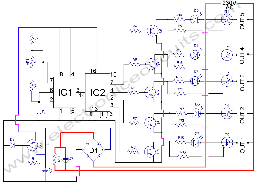
5 WAY AC FLASHER. These types of circuits are commonly used in various ceremonies such as the Wesak festival, Christmas, and weddings. This 5 WAY AC FLASHER circuit. The 5 Way AC Flasher circuit is designed to produce a sequential...
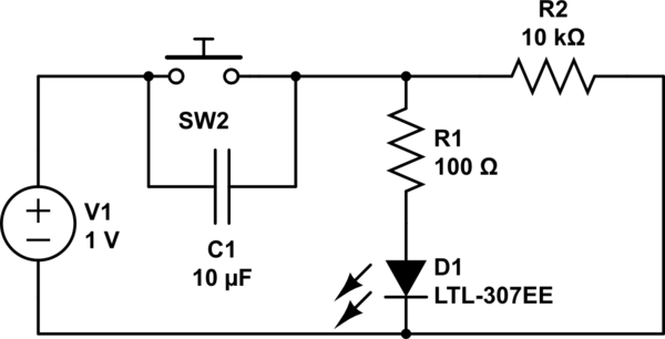
Understand why the LED does not light up, as the capacitor appears to be bypassing the switch. When the capacitor is fully charged, it does not conduct electricity. Although the individual is a beginner, after 20 hours of studying...

The R-C twin-tee passive circuit provides band-reject (notch) filtering suitable for portable applications. It has a loaded circuit Q of 0.25. Effective rejection is achievable when the bridge is balanced, which requires close tolerances of the adjustable components, and...
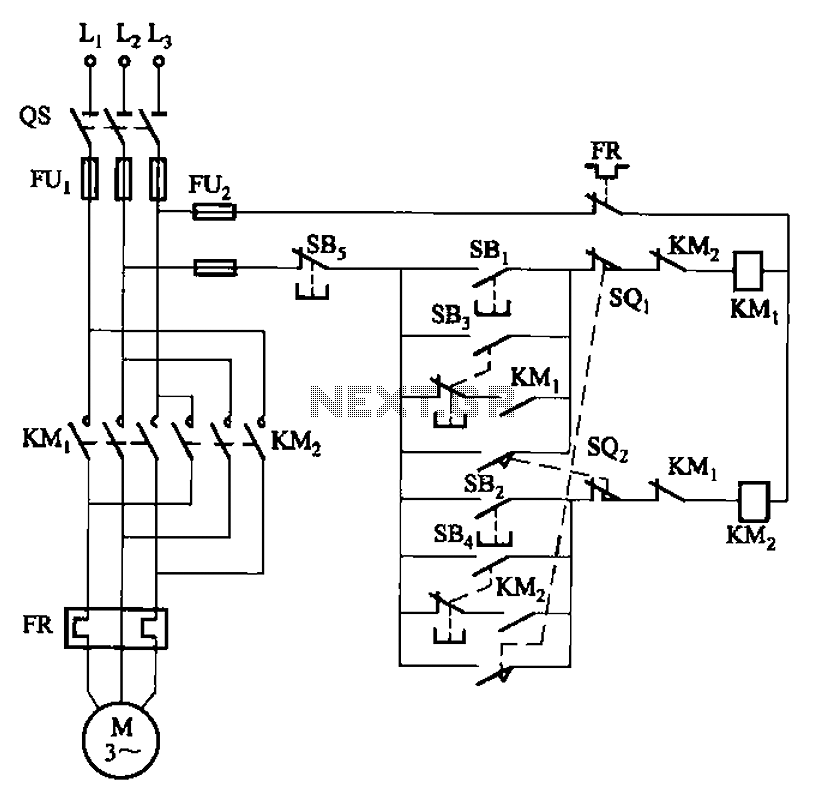
The circuit depicted in Figure 3-27 features a jog function that allows for precise adjustments of moving components. In the figure, SB3 and SB4 represent the forward jog and reverse jog buttons, respectively. When the SB3 button is pressed,...