
Light activated switch circuit

The described circuit utilizes the LM311 integrated circuit, which functions as a voltage comparator, to create a light-activated switch. The Light Dependent Resistor (LDR) serves as the primary sensor, responding to variations in light intensity. When the ambient light level falls below a certain threshold, the resistance of the LDR increases, resulting in a voltage change at the input of the LM311.
In this configuration, the LM311 compares the voltage across the LDR with a reference voltage set by a voltage divider composed of fixed resistors. The output of the LM311 is configured to switch on or off a connected load, such as an LED or relay, depending on the light level.
To construct this circuit, the following components are typically required:
- LM311 IC
- LDR (Light Dependent Resistor)
- Fixed resistors for the voltage divider
- A capacitor (optional for stability)
- A load (e.g., LED, relay)
- Power supply (typically +5V to +15V)
The circuit operates as follows:
1. The LDR is connected in series with a fixed resistor to form a voltage divider. The junction between the LDR and the resistor provides a variable voltage that changes with light intensity.
2. The output of this voltage divider is connected to one of the input pins of the LM311, while the other input pin is connected to a stable reference voltage.
3. When the light level decreases, the voltage from the voltage divider drops below the reference voltage, causing the LM311 to switch its output state.
4. The output can be used to drive a transistor or relay, which in turn activates or deactivates the load.
This circuit is widely applicable in automatic lighting systems, security alarms, and other light-sensitive applications, providing a simple yet effective solution for light-activated control.A simple light activated switch circuit with diagram and schematic using IC LM 311-wired as a voltage comparator and an LDR that acts as light sensor. 🔗 External reference
Related Circuits
This circuit diagram for a 12V inverter is simple to construct and utilizes inexpensive components that many electronics hobbyists may already possess. While it is feasible to create a more powerful circuit, the complexity arises from managing the significant...
A straightforward method to create a speaker transformer involves winding turns around a ferrite rod. The primary winding consists of 300 turns of 0.01mm wire, which is very fine, wound over the secondary and concluding with a loop of...
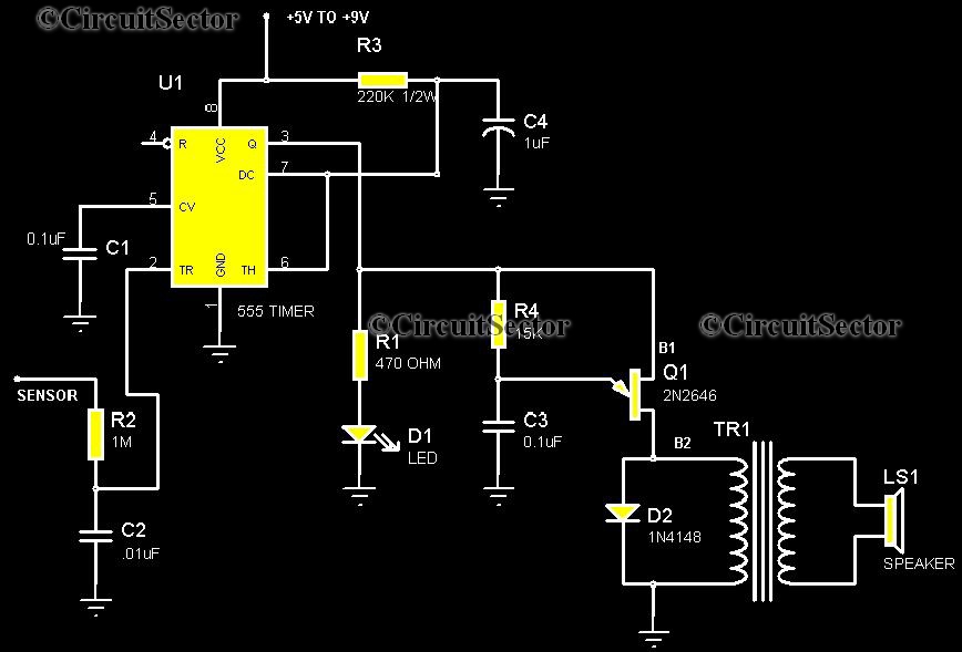
This is a highly sensitive touch plate circuit utilizing the NE555 timer IC, which activates a buzzer when a person touches the metal plate or hovers their hand above it. Compared to previously published touch control switch circuits, this...
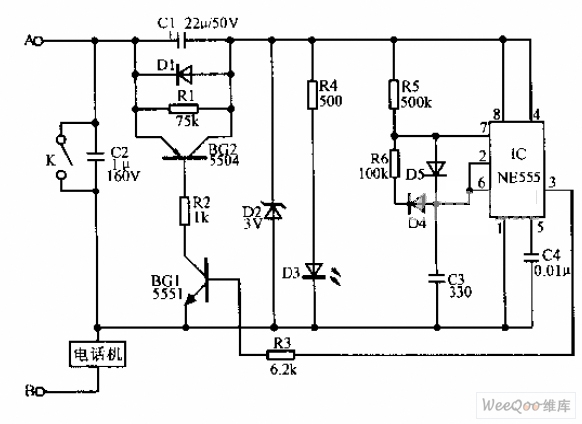
A simple telephone time lock circuit is depicted in the provided diagram. In this circuit, BG1 and BG2 function as electronic switches that are controlled by the IC NE555. When the telephone is on-hook, the DC resistance of the...
Before applying power, check for shorts on the board. This design operates from a 5V supply; connecting it directly to a 12V supply will certainly damage it. The current draw is minimal, approximately 70mA, so if using a 12V...
This page shows some methods of track routing control for Stall-Motor type switch machines. The principle method uses a 2 Pole - Multi Position rotary switch while an alternate uses optoisolators and transistors to select the routes. The last...