
Stall-Motor Routing Control Circuits

The described circuit implementations for track routing control in Stall-Motor type switch machines can be categorized into three primary methods: mechanical switching, electronic routing using optoisolators and transistors, and matrix control systems.
The first method employs a 2 Pole - Multi Position rotary switch. This hardware solution allows for straightforward manual control of the switch machine by physically rotating the switch to select the desired track route. Each position on the rotary switch corresponds to a specific route, making it intuitive for operators. The rotary switch typically connects to the Stall-Motor via a set of contacts that energize the motor in the desired direction, thus moving the switch points.
The alternate method utilizes optoisolators and transistors to facilitate electronic control of the routing. In this configuration, the optoisolators serve as a means to isolate the control signals from the high-power switch machine circuits, preventing any potential damage to the control system. When a control signal is received, the optoisolator activates a corresponding transistor, which then powers the Stall-Motor to move the switch points to the selected route. This method offers greater flexibility and can be integrated into automated systems, allowing for remote control and programming capabilities.
The final circuit method described involves electronic matrix control. This system utilizes a decoder to manage multiple routes, enabling complex routing configurations. The matrix consists of a grid where each intersection represents a potential track route. By employing a decoder, the system can select any route based on the binary input signals, thus allowing for an extensive number of route combinations. The limitation of this approach is primarily dictated by the size and complexity of the decoder used, which must be capable of handling the desired number of routes.
Collectively, these methods provide various options for implementing track routing control in model railroading and similar applications, each offering unique advantages based on the operational requirements and desired complexity of the control system.This page shows some methods of track routing control for Stall-Motor type switch machines. The principle method uses a 2 Pole - Multi Position rotary switch while an alternate uses optoisolators and transistors to select the routes. The last circuits on the page are for a method of controlling the matrix electronically. This would, in theory, allow any number of route selections, limited only by the size of the decoder.
🔗 External reference
Related Circuits
These two projects, Wah and Fuzz, are the results of a modification to a Morley dual channel volume control pedal that one of my sons suggested I undertake as he had no use for the volume unit but thought...
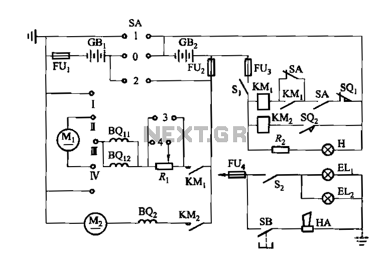
Denote cam controller SA 1 contact closure case. M1 is 1.35 kW driving motor, M2 is a 4 kW pump motor. The circuit involves a cam controller designated as SA 1, which is responsible for managing the operation of...
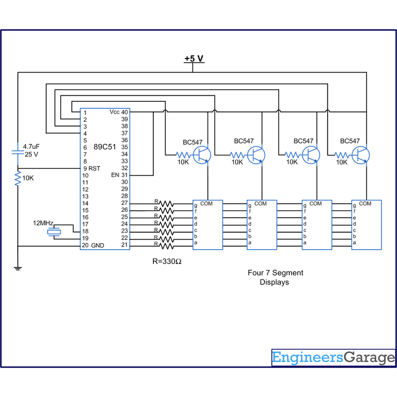
A digital clock displays time in a digital format. The circuit outlined here shows the time with double-digit minutes and two digits for seconds across four seven-segment displays. The segments of the displays are interconnected with the 8051 microcontroller...
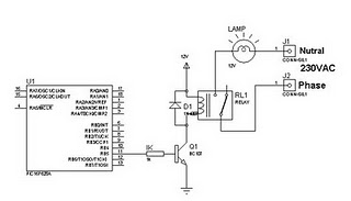
A relay can be controlled using a PIC microcontroller. The circuit illustrates how to control a single relay with the PIC 16F628. When the RB5 port of the PIC is set to high, the relay will activate. This circuit...
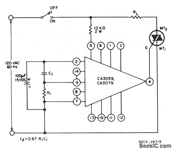
This circuit utilizes a CA3059 or CA3079 zero-voltage switch to manage the turn-on timing of a triac. The delay between the closure of the switch and the activation of the triac is determined by the resistor (R) and capacitor...
The following circuit illustrates a Bass-Treble Tone Control Circuit electronic diagram based on the LM1035N integrated circuit (IC). Features include a 0.3 Vrms input level, 80 dB signal noise ratio, 75 dB volume control, ±15 dB typical tone control,...