
Light Alarm

The described photo-sensing circuit utilizes a photo-transistor as the primary sensing element. When ambient light illuminates the photo-transistor, it generates a change in its conductivity. This change is detected by the 4011 NAND gate IC, which is configured to act as a signal amplifier and logic gate. The output of the 4011 is connected to a loudspeaker, allowing the circuit to produce sound in response to light exposure.
To construct the circuit, the following components are necessary: a photo-transistor, a 4011 NAND gate IC, a resistor for biasing the photo-transistor, and a loudspeaker. The photo-transistor should be oriented to receive light efficiently, and its collector-emitter junction can be connected to the input of the 4011. The resistor ensures that the photo-transistor operates within its optimal range, providing sufficient current to trigger the NAND gate when light is detected.
The 4011 NAND gate can be configured in such a way that it provides a low output when light is detected, which can be inverted if necessary to drive the loudspeaker directly or through a transistor for increased current handling. The loudspeaker will emit sound as a result of the output signal from the NAND gate, effectively creating an audio response to light.
This circuit is not only straightforward to assemble but also serves practical applications, such as light-activated alarms or sound-generating devices that respond to environmental changes.This is a simple Photo-sensing circuit. When light hits the photo-transistor, triggers the 4011 that drives a loudspeaker. Easy to make and can be very usefull too.
Related Circuits
The power failure light that I eventually designed and built is housed in the plastic case from a wall-mounted power transformer. I had accidentally destroyed the transformer by shorting its output, and had kept the plastic case for years,...
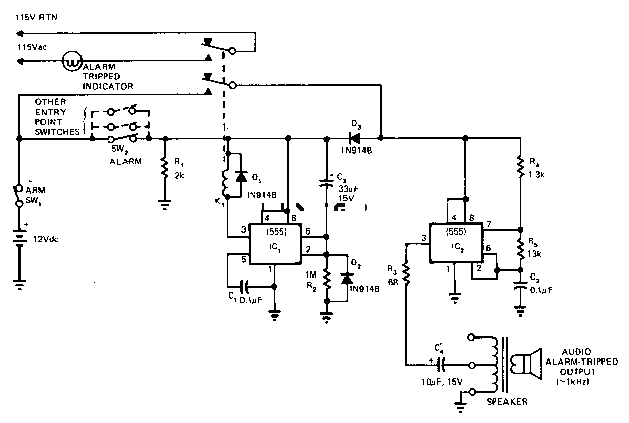
This circuit cannot be shut off for 10 to 60 seconds, even if the trip condition is immediately removed. It draws no standby power from the battery and is self-resetting. The described circuit operates under a delay mechanism that...
This circuit utilizes a 555 timer configured to operate in astable mode. This configuration produces a continuous output at Pin 3 in the form of a square wave. When the timer's output transitions to a high state, it triggers...
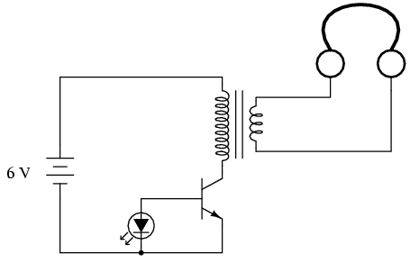
If you do not have an audio detector already constructed, a set of closed-cup audio headphones that completely cover the ears, along with a 120V/6V step-down transformer, can be utilized to create a sensitive audio detector for this experiment....
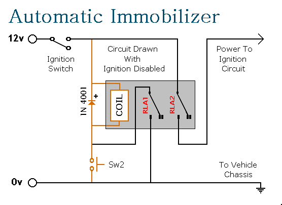
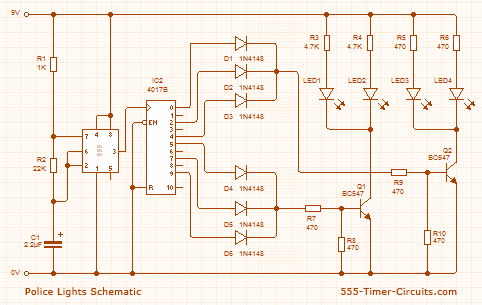
This circuit features automatic exit and entry delays, an optional instant alarm zone, an optional intermittent siren output, and an automatic reset. By adding external relays, the vehicle can be immobilized and the lights can be flashed. The alarm...
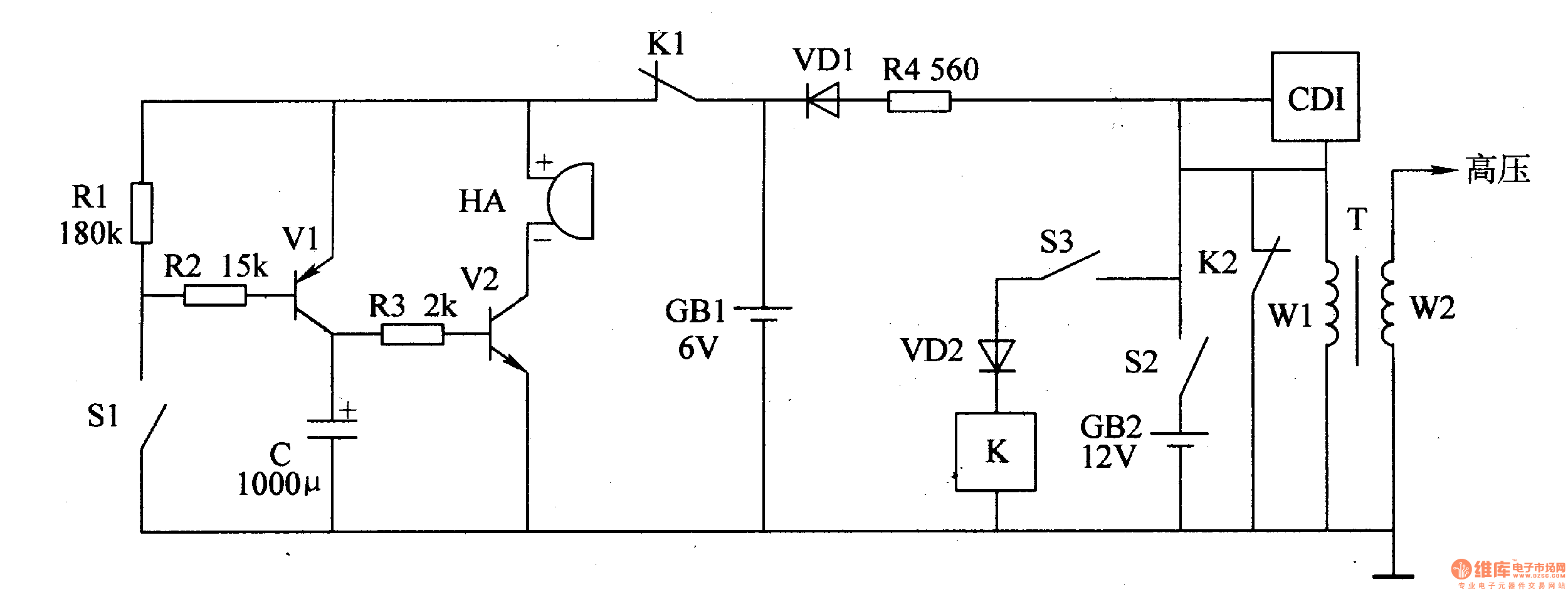
The motorcycle anti-theft alarm circuit consists of a detection alarm circuit, a charging circuit, and an anti-theft control circuit, as illustrated in figure 7-94. The detection alarm circuit includes a mercury switch (S1), resistors (R1-R3), a capacitor (C), transistors...