
Pulsed-light sensor

The audio detector circuit described utilizes a light-emitting diode (LED) as the core sensing element. The LED, when exposed to varying light conditions, generates small electrical signals that require amplification for audible output. The circuit is initiated by connecting the LED to a transistor configured as a common emitter amplifier. The transistor amplifies the small current generated by the LED, allowing it to drive the headphones effectively.
In practical implementation, the circuit can be powered using a 120V to 6V step-down transformer, which ensures that the voltage supplied to the circuit is safe and manageable. The transformer is connected to the mains supply, and its output is fed into the circuit, providing the necessary voltage to the LED and transistor.
The LED is positioned to face the light source, and its sensitivity can be adjusted based on the ambient light conditions. For optimal performance, the circuit can be enclosed in a housing that minimizes external light interference while allowing the desired light source to reach the LED. The headphones are connected to the output of the transistor, where the amplified audio signal is delivered.
This audio detector circuit is particularly effective with light sources that produce rapid fluctuations in intensity, such as fluorescent and neon lamps. The 60 Hz flicker of these lamps creates a pulsing effect that the LED can detect, resulting in an audible tone in the headphones. Additionally, the circuit can be tested outdoors using sunlight, where moving objects can create varying light conditions that the LED can pick up.
The ability of LEDs to function as both light emitters and detectors opens up possibilities for innovative applications, including wireless audio transmission. By integrating a suitable transmitter circuit that modulates the LED with an audio input, it becomes feasible to transmit sound over a light beam, which the described receiver circuit can then decode back into audible signals. This principle underlies many optical communication systems and can be a foundational experiment for understanding light-based data transmission.If you don`t have an audio detector already constructed, you can use a nice set of audio headphones (closed-cup style, that completely covers your ears) and a 120V/6V step-down transformer to build a sensitive audio detector without volume control or overvoltage protection, just for this experiment. If you haven`t made an audio detector as outlined in both the DC and AC experiments chapters, you really should - it is a valuable piece of test equipment for your collection. This circuit detects pulses of light striking the LED and converts them into relatively strong audio signals to be heard through the headphones. Forrest Mims teaches that LEDs have the ability to produce current when exposed to light, in a manner not unlike a semiconductor solar cell.
[MIM] By itself, the LED does not produce enough electrical power to drive the audio detector circuit, so a transistor is used to amplify the LED`s signals. If the LED is exposed to a pulsing source of light, a tone will be heard in the headphones. Sources of light suitable for this experiment include fluorescent and neon lamps, which blink rapidly with the 60 Hz AC power energizing them.
You may also try using bright sunlight for a steady light source, then waving your fingers in front of the LED. The rapidly passing shadows will cause the LED to generate pulses of voltage, creating a brief "buzzing" sound in the headphones.
LEDs serving as photo-detectors are narrow-band devices, responding to a narrow band of wavelengths close, but not identical, to that normally emitted. Infrared remote controls are a good illumination source for near-infrared LEDs employed as photo-sensors, producing a receiver sound.
[MIM3] With a little imagination, it is not difficult to grasp the concept of transmitting audio information - such as music or speech - over a beam of pulsing light. Given a suitable "transmitter" circuit to pulse an LED on and off with the positive and negative crests of an audio waveform from a microphone, the "receiver" circuit shown here would convert those light pulses back into audio signals.
[MIM2] 🔗 External reference
Related Circuits
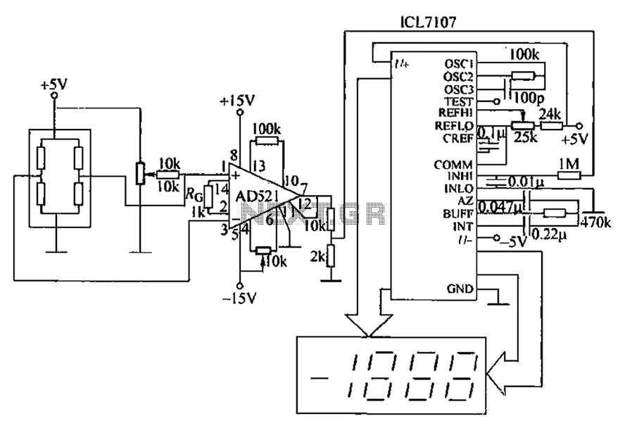
A pressure sensor circuit features a pressure sensor with a nominal resistance of 120 ohms. The amplifier circuit utilizes an AD521 operational amplifier with a gain of 100. It includes resistor components Rs and Rc, along with a decision-making...
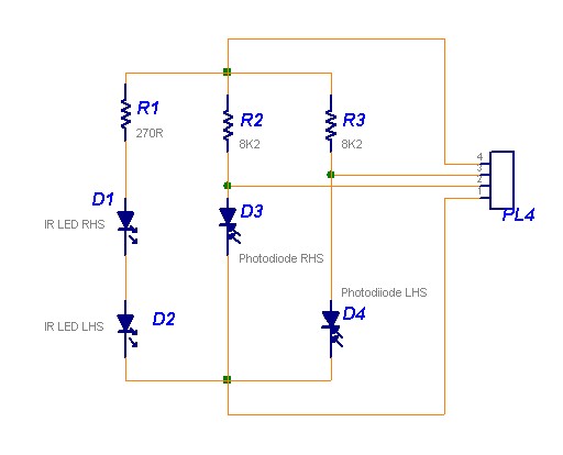
The following circuit illustrates a Line Follower Sensor Circuit Diagram. Features include a simple design, with Infrared LEDs D1 and D2 emitting infrared light. The Line Follower Sensor Circuit is designed to detect the presence of a line, typically a...
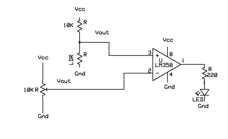
A light-based sensor utilizing an LDR (Light Dependent Resistor) and an operational amplifier (Op Amp). This circuit can be employed for applications such as line followers. The operation of the Op Amp is foundational to this design. It features...
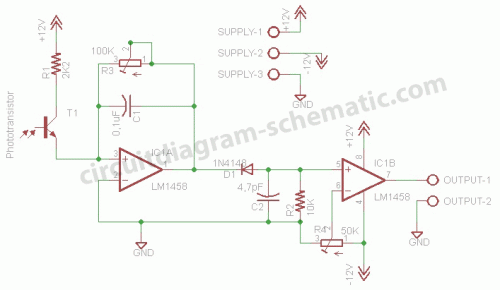
This circuit is a motion detection sensor that utilizes a light source and detector as an infrared motion detector. The motion sensor employs an infrared LED and a phototransistor. Since it relies on light, the sensor's sensitivity can be...
Bridged resistive sensing elements are commonly used in resistive type sensors and transducers. This type of sensor requires a biasing voltage to operate. The LM10 provides low... Bridged resistive sensing elements are integral components in various resistive sensors and transducers,...

This light sensor switch circuit enables the automatic activation of a lamp when ambient light levels are low, such as during nighttime. The circuit keeps the lamp illuminated for a predetermined duration. When transistors T4 and T5 are activated,...