
Light control relay circuit

The described photoelectric switch circuit employs a photoresistor (also known as a light-dependent resistor, LDR) as the primary sensing element. The photoresistor's resistance varies inversely with the intensity of incident light; thus, in low-light conditions, its resistance is high, preventing the base of the transistor (VT) from receiving adequate current. Consequently, the transistor remains in the off state, and no current flows through the relay coil, keeping the relay contacts open.
As the ambient light increases and surpasses a predetermined threshold, the resistance of the photoresistor decreases. This change allows a sufficient amount of current to flow into the base terminal of the transistor. The transistor enters saturation, which significantly increases the collector current. This current is sufficient to energize the relay coil, closing the relay contacts and allowing current to flow through the load connected to the relay.
The circuit typically includes additional components such as resistors to limit current and capacitors for noise filtering, ensuring stable operation. The relay can control various devices, from simple light fixtures to complex systems, depending on the design requirements. The high sensitivity of the circuit makes it suitable for applications where precise light detection is critical, such as in automatic lighting systems, security systems, and other automation applications. Proper calibration of the photoresistor and the selection of the transistor are essential for achieving optimal performance in varying lighting conditions.As a photoelectric switch with photoresistor circuit, the sensitivity is very high, as shown for the light control relay. At low illumination, VT nonconductive; when there is l ight of a certain illumination, photoresistor resistance becomes smaller, VT sufficient base current conduction, resulting in a large collector current, so that relay.
Related Circuits
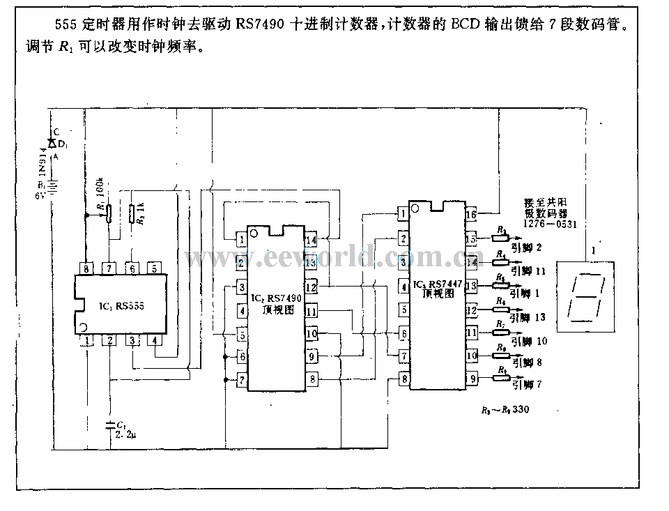
The 555 timer is utilized as a clock source to drive the RS7490 decimal counter, providing a BCD output to a 7-segment LED display. The clock frequency can be adjusted by changing the value of resistor R1. The circuit operates...
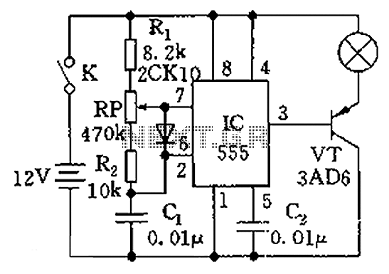
The circuit illustrated in the figure is a dimmer using the 555 timer as the core component. The 555 timer, along with resistors R1, RP, R2, and capacitor C1, forms an astable multivibrator. The oscillation frequency, f, is calculated...
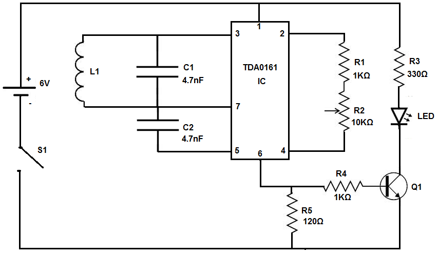
The device being constructed will serve as a metal detector, capable of locating metal objects such as coins, nails, and keys, including car keys that may be misplaced. It can also detect gold, although it may not possess industrial...
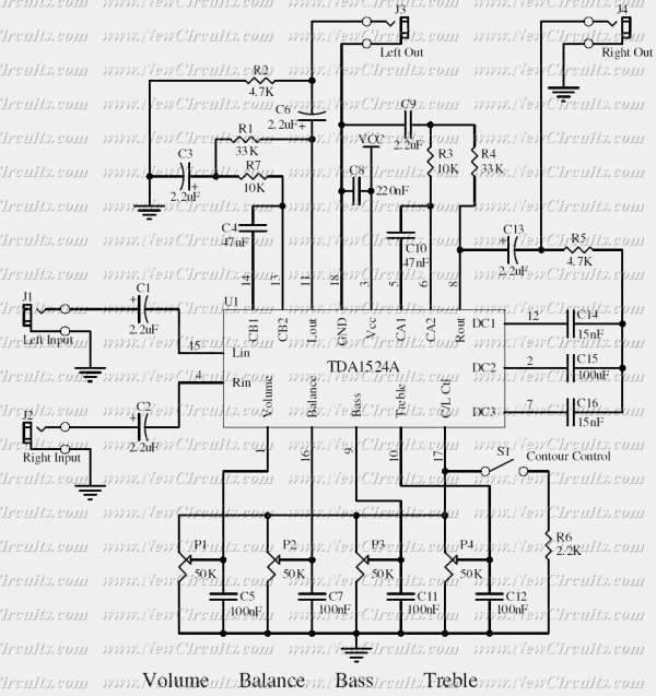
This simple tone control can be used in many audio applications. It can be added to amplifiers, used as a stand-alone control module, or even built into new and exciting instruments. Its one IC construction makes it a very...
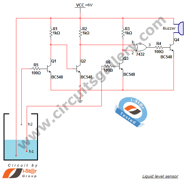
A variety of small electronic projects related to water level sensors have been posted in the Circuits Gallery. This particular project is designed for school students to detect the water level within a water tank or any other water...
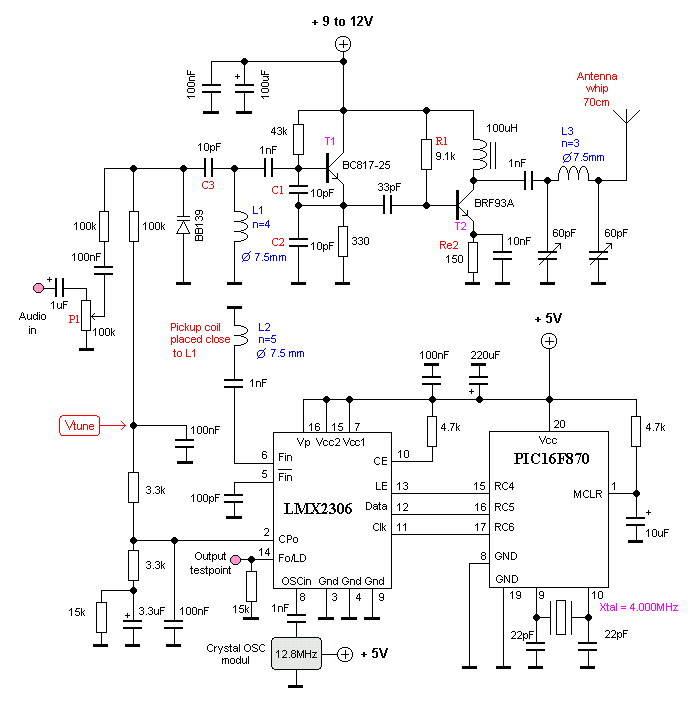
This oscillator is known as the Colpitts oscillator and is voltage-controlled to facilitate frequency modulation (FM) and phase-locked loop (PLL) control. The transistor T1 should be a high-frequency (HF) transistor for optimal performance; however, in this instance, a common...