
Light Controlled Relays

The described circuit consists of two light-sensitive relay control circuits, each utilizing a Light Dependent Resistor (LDR) to detect ambient light levels. The first circuit activates the relay when the light intensity exceeds a predetermined threshold, while the second circuit activates the relay when the light intensity drops below this threshold.
Both circuits are designed similarly, with the primary distinction being the orientation of the transistor used in each circuit. This bipolar junction transistor (BJT) configuration allows for the switching of the relay based on the light levels detected by the LDR. The LDR's resistance decreases with increasing light levels, which allows for the modulation of the voltage at the transistor's base, effectively controlling the relay's state.
The circuit operates by monitoring the voltage levels at pins 5 and 6, which are critical for determining the relay's activation state. The selection of the LDR is flexible, as any LDR can be used satisfactorily; however, the resistance value of R1 may need adjustment to fine-tune the sensitivity and range of the light detection. This adjustment will ensure that the circuit accurately responds to the specific light conditions required for the application.
It is crucial to note that the on-board relay should not be used for switching mains voltage due to insufficient isolation between the relay contacts and the low-voltage components on the board. For applications requiring mains voltage switching, it is recommended to use an appropriately rated relay mounted in a secure location, ensuring compliance with safety standards and preventing potential hazards associated with electrical isolation.The first circuit energizes the relay when the light rises above the preset level. The second circuit energizes the relay when the light falls below the preset level. The two circuits are practically identical. The only difference between them is the polarity of the transistor. The value of the LDR is not critical. The important thing is the voltage on pins 5 & 6. Any value LDR should work satisfactorily. But you may need to change the value of R1 - to achieve the desired range of adjustment. Do not use the "on-board" relay to switch mains voltage. The board's layout does not offer sufficient isolation between the relay contacts and the low-voltage components. If you want to switch mains voltage - mount a suitably rated relay somewhere safe - 🔗 External reference
Related Circuits
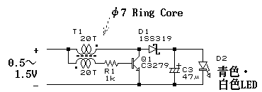
This is a pocket-sized LED flashlight operating with only one AAA battery. However, the super high luminosity LEDs (blue, green, or white) require at least 3.5 volts of forward voltage. This flashlight is boosting input voltage up to the...
It is the essential continuity of circuits Sel 8 Sources and Up/Down Sel 8 Sources, but can work and autonomously, collaborating with any suitable circuit of control. The Relay 1-8 can be 6-24v DC. For current of collector of...
Lamp dimmer. The circuit illustrated below can be employed for dimming lamps. It utilizes a minimal number of components, which can be conveniently installed within the lamp socket. This circuit is typically utilized in RC phase shift configurations. The...
The motion games on the Nokia 5800 sparked an interest in creating a real-world version of a racing car controlled by tilting a phone. The motion-controlled robot, named Hercules due to its high torque and speed, is operated via...
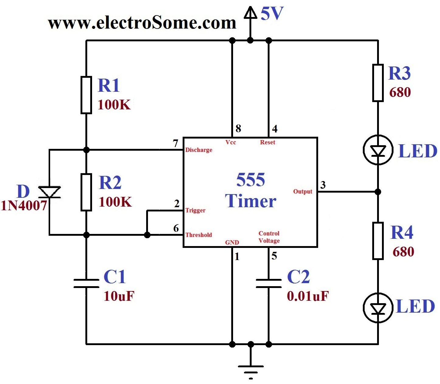
A dancing light can be easily constructed using a 555 timer wired in astable mode. This circuit alternately blinks two LEDs with a certain delay and can be modified to include additional LEDs or to control incandescent lamps. The...
A DC supply of +5 V is obtained from a 230 V AC source. This power supply is utilized by other circuit blocks. A pulse generator operating at a specific frequency generates clock pulses. These clock pulses are counted...