
6 Channel Auto Reverse Sequential Disco Running Lightss

The circuit begins with a power supply that converts 230 V AC to a stable +5 V DC output, ensuring that the subsequent components operate within their required voltage specifications. This DC supply is essential for powering the pulse generator and the integrated circuits involved in the operation.
The pulse generator, implemented using an IC 555, operates in astable mode to produce a continuous stream of clock pulses. The frequency of these pulses can be adjusted by selecting appropriate resistor and capacitor values in the circuit, allowing for flexibility in the operation of the entire system. The generated clock pulses are fed into an IC 4017, which functions as a decade counter. The IC 4017 counts the incoming pulses and provides an output signal after every 10 pulses, effectively creating a controlled sequence for the subsequent components.
The output from the IC 4017 is used to drive a series of transistors configured as switches. These transistors are crucial for controlling the triacs, which are semiconductor devices that allow current to flow in both directions. When the transistors are activated by the output from the counter, they trigger the corresponding triacs, enabling them to conduct and supply power to the connected load.
In this circuit, decorative bulbs are utilized as the load for each triac. The design allows for sequential activation of the bulbs, with the triacs turning them ON and OFF in a programmed sequence. This not only creates an appealing visual effect but also demonstrates the capability of the circuit to control AC loads using low-voltage DC signals.
The operation of the circuit can be enhanced by incorporating additional features such as variable pulse frequency, dimming capabilities, or even remote control functionalities, depending on the application requirements. Overall, this schematic effectively showcases the integration of various electronic components to achieve a specific control mechanism for AC loads using a simple yet effective counting and triggering system.From 230 V AC a DC supply of + 5 V is obtained. The power supply is given to the other blocks. The pulse generator at a particular frequency generates the clock pulses. The clock pulses are counted by a counter and gives output after every 10 pulses. The counter drives the transistors, which form the triac firing circuit. The transistors fire thetriacs and they provide sufficient current to the load. Decorative bulbs are connected as load for each triac. The bulbs are sequentially turned ON and OFF in forward and reverse way. The IC 555 works as the pulse generator and feeds the clock pulses to IC 4017. IC 4017 is the heart of this circuit. It works as a counter and gives the output after every 10 pulses. It drives the transistors, which in turn fire the triacs. The triac provides sufficient current to the load. 🔗 External reference
Related Circuits
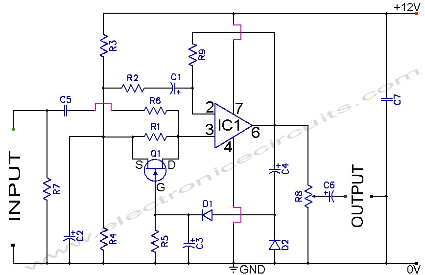
A section of the operational amplifier's output signal is rectified using 1N4148 diodes, followed by filtering, and is then directed to the gate of the FET input shunting circuit. As the output voltage increases, additional input shunting occurs, which...
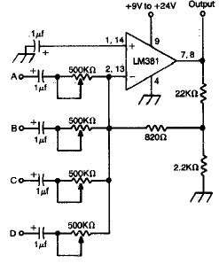
LM381 4-channel audio mixer circuit design project using a few common electronic parts. The LM381 audio mixer circuit is designed to combine audio signals from four separate channels into a single output. This circuit employs the LM381 integrated circuit, which...
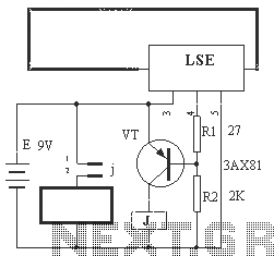
The circuit operation principle of the device illustrated in Figure 13 is as follows: When the barbed wire (Fe) remains intact, the output pin (O) of the LSE is at a high state. Consequently, the transistor (VT) remains off,...

Transistor Q1 can be a 2N2222(A), 2N3904, NTE123A, ECG123A, etc. Not critical at all. It acts only as a switch for the relay so almost any type will work, as long as it can provide the current needed to...
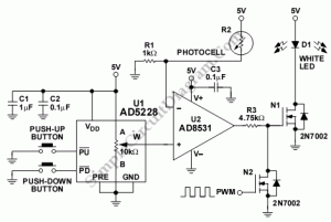
The following circuit illustrates the use of the AD8531 integrated circuit for the automatic control of LCD panel backlighting. Features include the ability to compensate for aging effects. The AD8531 is a precision operational amplifier that is well-suited for applications...
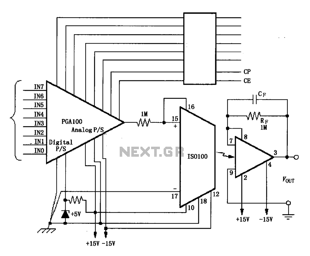
The ISO100 multichannel data acquisition system comprises a programmable gain amplifier isolated by an optocoupler, a programmable amplifier (PGA100), and an isolation amplifier (ISO100). The optocoupler selects three channels and is coupled to the programmable gain amplifier, which can...