
Light Detector circuit

Part List
R1=270ohm C1-2=100nF 100V ceramic IC2=74HCT13
R2-5=1Kohm RV1=10Kohm trimmer Q1=BP103 Phototransistor Siemens
R3=10Kohm D1-2=1N4148
R4=100ohm IC1=CA3130
This light detection circuit is designed to monitor ambient light levels and provide a corresponding output signal. The core functionality relies on a phototransistor (Q1), specifically the BP103 model from Siemens, which is sensitive to light. When the phototransistor detects sufficient light, it allows current to flow, resulting in a low logic level output compatible with TTL (Transistor-Transistor Logic) standards.
The circuit includes several resistors (R1, R2, R3, R4) and a trimmer potentiometer (RV1) that adjusts the sensitivity of the phototransistor. The trimmer allows for fine-tuning, enabling the user to set the threshold at which the output changes state based on light intensity. R1, with a value of 270 ohms, may be used to limit the current flowing through the circuit, while R2 and R3 (both 1K ohms) help establish biasing conditions for the phototransistor. R4, at 100 ohms, may serve to protect the output stage from excessive current.
Capacitor C1-2 (100nF, 100V ceramic) is included to filter noise and stabilize the power supply, ensuring reliable operation of the circuit. The use of the CA3130 operational amplifier (IC1) enhances the circuit's performance by providing a means to amplify the signal from the phototransistor. The output from the CA3130 can be fed to the 74HCT13 (IC2), a quad 2-input NAND gate, which can be used to further process the signal or interface with other digital logic circuits.
Diodes D1-2 (1N4148) may serve as protection devices, preventing back-emf or reverse voltage that could damage the sensitive components in the circuit. Overall, this light detection circuit can be effectively utilized in applications such as automatic lighting systems, where lights need to be turned on or off based on ambient light conditions.This circuit give low level output, when exist enough lighting, that is a detector of light. It can give, say ,command turn on somebodies lights, when fall the dark. His exit is compatible with TTL level and it give low logic level, when phototransistor Q1, detect light. With adjustable resistor RV1, we can regulate the sensitivity that it will have. Part List R1=270ohm C1-2=100nF 100V ceramic IC2=74HCT13 R2-5=1Kohm RV1=10Kohm trimmer Q1=BP103 Phototransistor Siemens R3=10Kohm D1-2=1N4148 R4=100ohm IC1=CA3130 🔗 External reference
Related Circuits

Before applying power, check for shorts on the board. This design operates from a 5V supply; connecting it directly to a 12V supply will certainly damage it. The current draw is minimal, approximately 70mA, so if using a 12V...
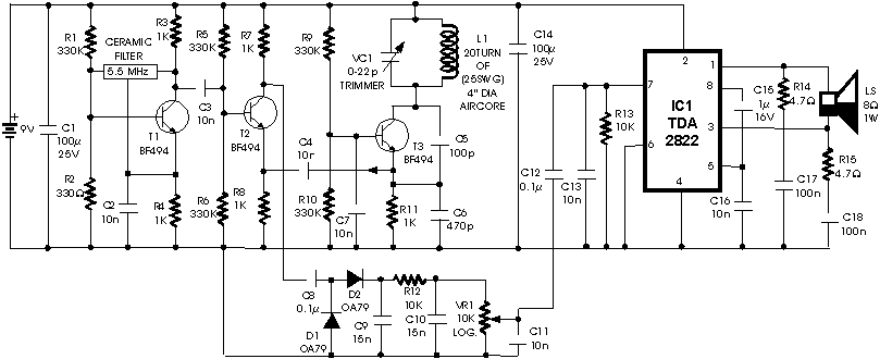
The circuit described is a metal detector. The operation of the circuit is based on the superheterodyne principle, which is commonly used in superheterodyne receivers. The circuit utilizes two RF oscillators, both fixed at a frequency of 5.5 MHz....
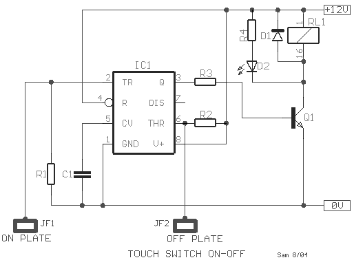
This type of sensor switch is ideal for creating touch-operated bells and buzzers in small toys, which function for a limited duration before automatically shutting off. The trigger's input impedance is very high, allowing the touch sensor switch to...
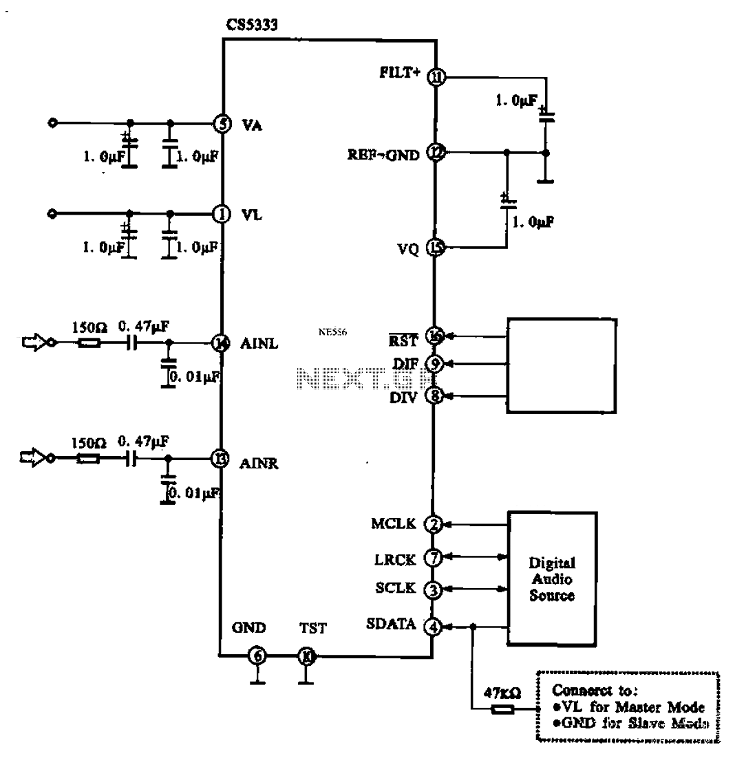
Audio A/D converter circuit configuration using the CS5333 chip, which is a high-performance 24-bit, 96 kHz stereo A/D converter commonly used in digital products. This circuit converts one or more audio signals into a digital signal for processing and...
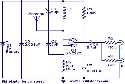
This compact FM adapter circuit, when connected to the audio output of a cassette player or iPod, enables the user to listen to their favorite music through a car stereo. It is particularly useful for vehicles that lack an...
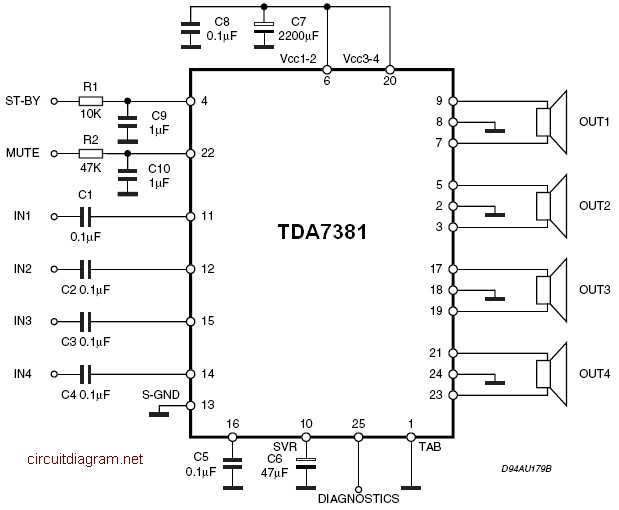
The amplifier is a quad amplifier circuit (amplifier with four inputs and four outputs) based on the TDA7381. This amplifier is designed for car audio systems, but it can also be utilized for other applications. The circuit has a...