
Audio Metal Detector Schematic

The metal detector circuit operates on the principle of frequency modulation and demodulation. The two RF oscillators generate signals that are mixed to produce a beat frequency, which is an essential part of the detection mechanism. The first oscillator, using a crystal filter for stability, ensures a reliable reference frequency. The second oscillator, being a Colpitts type, allows for easy frequency adjustments through the trimmer capacitor, enabling fine-tuning for optimal sensitivity.
The mixer stage is crucial as it combines the signals from the two oscillators. The choice of BF494 transistors for both the oscillators and the mixer ensures low noise and good performance at RF frequencies. The output from the mixer is rectified by the diodes, converting the alternating current (AC) signal into a direct current (DC) signal that varies with the presence of metal.
The low-pass filter composed of the resistor and capacitors effectively smooths the pulsating DC signal, allowing only the desired audio frequency to pass through to the amplifier. The variable control allows the user to adjust the gain of the audio output, making the circuit adaptable to various environments and metal types.
The inductor L1's design is critical for the circuit's sensitivity. The air-core construction minimizes losses and provides a good response to changes in inductance caused by nearby metal objects. The careful assembly and securing of the inductor with varnish ensure durability and consistent performance.
Overall, this metal detector circuit is a practical application of RF technology and audio amplification, demonstrating the principles of oscillation, mixing, and signal processing in a compact and functional design.The ambit declared actuality is that of a metal detector. The opera- tion of the ambit is based on superheterodyning assumption which is frequently acclimated in superhet receivers. The ambit utilises two RF oscillators. The frequencies of both oscillators are anchored at 5. 5 MHz. The aboriginal RF oscillator comprises transistor T1 (BF 494) and a 5. 5MHz bowl clarify frequently acclimated in TV sound-IF section. The additional oscillator is a Colpitt ½s oscillator realised with the advice of transistor T3 (BF494) and inductor L1 (whose architecture capacity follow) shunted by trimmer capacitor VC1. These two oscillators ½ frequencies (say Fx and Fy) are alloyed in the mixer transistor T2 (another BF 494) and the aberration or the exhausted abundance (Fx-Fy) achievement from beneficiary of transistor T2 is affiliated to detector date absolute diodes D1 and D2 (both OA 79).
The achievement is a pulsating DC which is anesthetized through a low-pass clarify realised with the advice of a 10k resistor R12 and two 15nF capacitors C6 and C10. It is again anesthetized to AF amplifier IC1 (2822M) via aggregate ascendancy VR1 and the achievement is fed to an 8-ohm/1W speaker.
The inductor L1 can be complete application 15 turns of 25SWG wire on a 10cm (4-inch) bore air-core above and again cementing it with careful varnish. For able operation of the ambit it is analytical that frequencies of both the oscillators are the aforementioned so as to access aught exhausted in the absence of any metal in the abreast around of the circuit.
The alignment of oscillator 2 (to bout oscillator 1 frequency) can be done with the advice of trimmer capacitor VC1. When the two frequencies are equal, the exhausted abundance is zero, i. e. exhausted frquency=Fx-Fy=0, and appropriately there is no complete from the loudspeaker. When chase braid L1 passes over metal, the metal changes its inductance, thereby alteration the additional oscillator ½s frequency.
So now Fx-Fy is not aught and the loudspeaker sounds. Appropriately one is able to ascertain attendance of metal 🔗 External reference
Related Circuits
This circuit uses two quad op-amps to form an eight LED audio level meter. The op-amp used in this particular circuit is the LM324. It is a popular IC and should be available from many parts stores. The 1K...
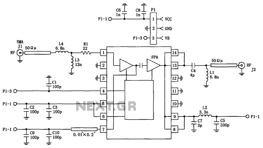
The circuit illustrated in FIG consists of the RF2103P 915MHz RF amplifier circuit. P1 serves as the outlet, where P1-1 connects to power Vcc, P1-2 connects to ground, and P1-3 is used for the power down control voltage VB....
Here a simple design for an attractive tone. They operate on a passive principle, ie without amplification. The circuit only weakened and therefore require no power. As can be seen, the circuit is built with two T-filters in the...
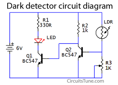
This is a basic dark detector or sensor circuit diagram based on a photoresistor (LDR) and a few components. The dark detector circuit utilizes a photoresistor (LDR) as the primary sensing element. The LDR is a light-dependent resistor that changes...
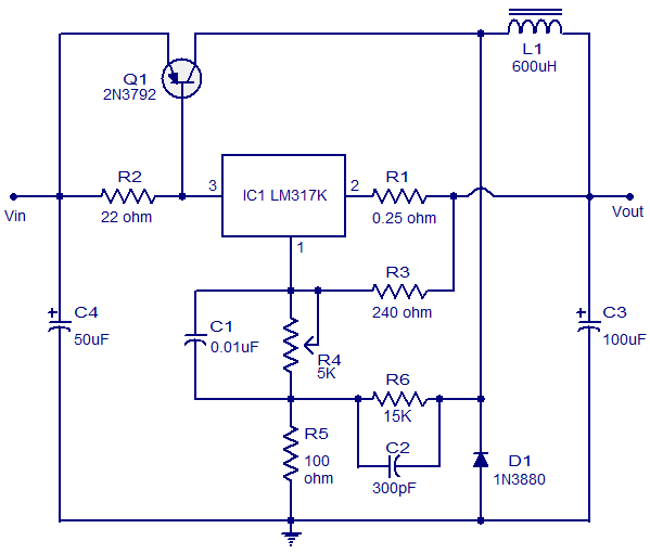
This circuit illustrates a 3A Switching Regulator Circuit based on the LM317K integrated circuit. It is designed to be simple and cost-effective. The 3A Switching Regulator Circuit utilizing the LM317K IC serves as a versatile voltage regulation solution, capable of...

This document presents an audio amplifier circuit suitable for use in walkie-talkies, low-power transmitters, and packet radio receivers. The circuit utilizes a condenser microphone audio amplifier that delivers high-quality audio output of 0.5 watts at 3 volts. The design...