
Light Dimmer/Speed Control

The phase-controlled triac circuit utilizing the HT-32 component is designed for effective voltage regulation at the load, allowing for precise control in various applications. The circuit operates by adjusting the phase angle of the AC voltage, which effectively modifies the amount of power delivered to the load. This method of control is particularly useful in applications such as light dimmers, motor speed controllers, and heating elements.
In this configuration, the inclusion of inductive elements (LI) and capacitor (C4) is crucial for radio frequency interference (RFI) suppression. LI serves to limit high-frequency noise that may arise from the switching action of the triac, while C4 acts as a filter to smooth out voltage spikes and transients, ensuring stable operation and compliance with electromagnetic compatibility (EMC) standards.
The circuit is rated for a maximum load of approximately 500 W, which indicates its suitability for moderate power applications. It is imperative to observe safety precautions, particularly due to the presence of 120 Vac within the circuit. Proper insulation techniques, such as using heat-shrink tubing and insulated connectors, alongside robust construction practices, must be employed to prevent electrical hazards.
Overall, this triac-based circuit exemplifies a reliable solution for controlling AC power with the added benefits of RFI suppression, making it an effective choice for various electronic applications. A phase-controlled triac (HT-32) circuit provides control of effective voltage at load. Do not omit LI and C4 be cause they are for RFI suppression. The maximum load is about 500 W. WARNING: 120 Vac is present on this circuit—provide adequate insulation and construction techniques.
Related Circuits
The Intelligent Fan Controller regulates the speed of computer fans according to the internal temperature of the computer, minimizing noise levels. It utilizes a 4-wire, 2-wire, and 3-wire fan configuration in conjunction with a PIC microcontroller, specifically the PIC18F2550....
The circuit utilizes a 555 timer integrated circuit (IC) configured as an astable multivibrator. The flashing rate can be adjusted from very fast to a maximum of once every 1.5 seconds by changing the setting of the preset variable...
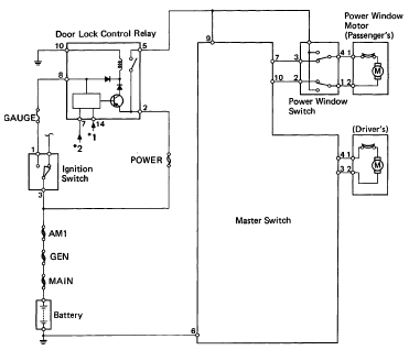
The following circuit illustrates the 1993 Toyota Hilux Pickup Power Window Control System Electrical Circuit Diagram. It is beneficial for both personal use and for mechanics during repairs. Key components include the door lock relay, junction block, power window...
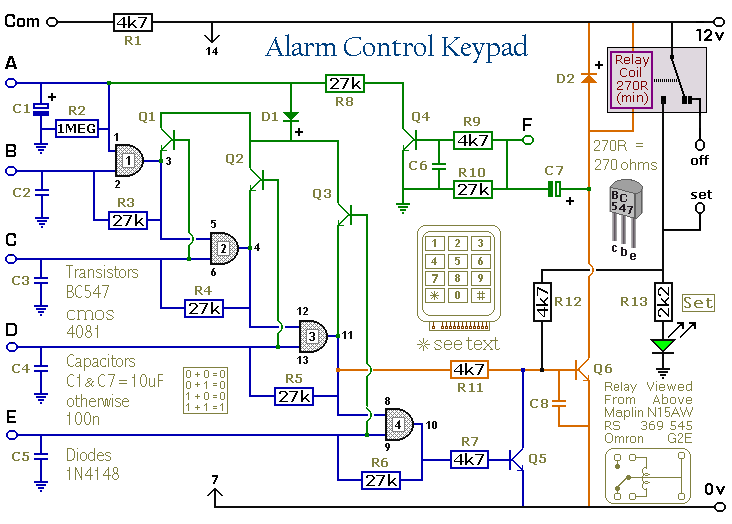
This keypad is designed for use with the Modular Burglar Alarm system, although it can be applied in various other contexts. Inputting the first four digits of a selected five-digit code will activate the relay, while entering the complete...
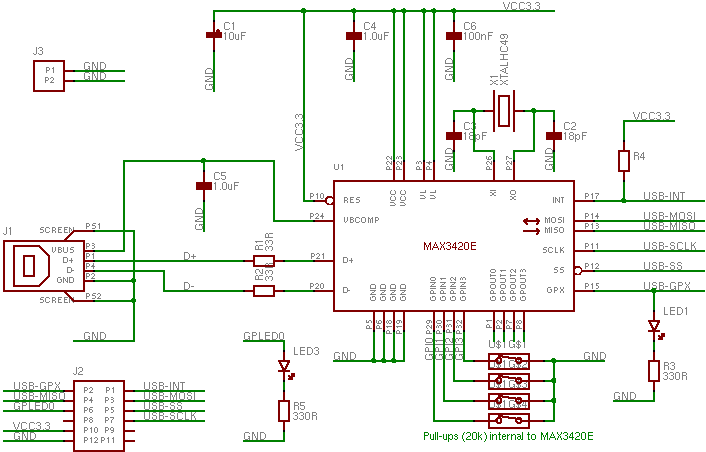
The MAX3420 is a USB peripheral controller chip featuring an SPI bus. This document aims to provide sufficient information for effective utilization of the device in various projects. The MAX3420 simplifies the integration of a USB interface into a...
This is a circuit for controlling the speed of small DC motors; it works nicely as a speed controller for an HO or N gauge model railroad. More: The left half of the 556 dual timer IC is used...