
5 digit alarm control keypad

The keypad operates as a secure input interface for alarm systems, allowing users to manage the state of the system through a numeric code. The design typically includes a matrix of keys, each corresponding to a digit, which are arranged to facilitate easy access and input.
When the first four digits of the code are entered, the internal logic of the keypad processes this input and sends a signal to energize a relay. The relay acts as a switch that can control various outputs, such as triggering an alarm or activating other devices within the security system.
The complete five-digit code serves a dual purpose: once entered, it signals the system to deactivate the relay, effectively disarming the alarm or switching off the connected devices. This feature enhances security by requiring users to remember a longer code to fully disengage the system, thus preventing unauthorized access.
In terms of electrical specifications, the keypad typically operates on a low-voltage power supply, often in the range of 5V to 12V DC, making it suitable for integration into various alarm systems. The relay output may be rated for higher voltages and currents, allowing it to interface with standard alarm systems or other electronic devices.
Additional features may include backlighting for visibility in low-light conditions, audible feedback for key presses, and a tamper switch that can trigger an alert if the keypad is removed from its mounting. Overall, the keypad is a versatile component that enhances the functionality and user interface of modular alarm systems and can be adapted for other applications requiring secure numeric input.This Keypad is suitable for the Modular Burglar Alarm. However, it has other applications. Entering the First Four Digits of your chosen Five-Digit code - will energize the relay. Entering the Full Five-Digit code - will de-energize it.. 🔗 External reference
Related Circuits
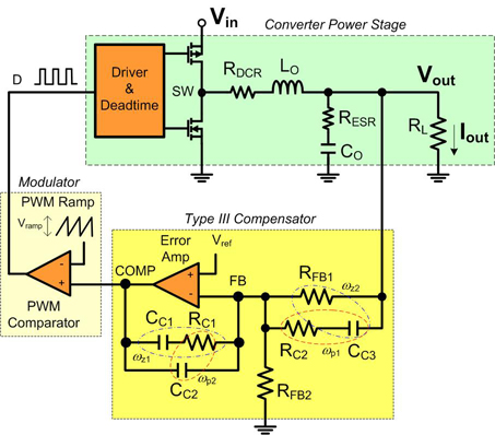
Before designing with one of today's powerful buck regulator ICs, it is essential to have a thorough understanding of voltage mode control and compensation. Voltage mode control is a widely used method in switching power supplies, particularly in buck converters....
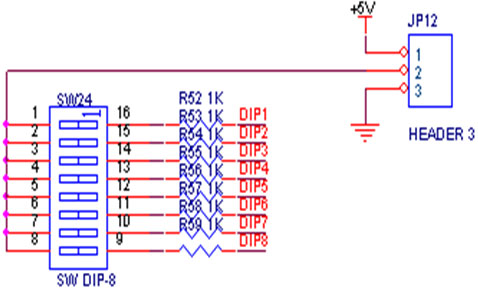
A switch is an electrical component that can break an electrical circuit, interrupting the current or diverting it from one conductor to another. A switch may be directly manipulated by a human as a control signal to a system...
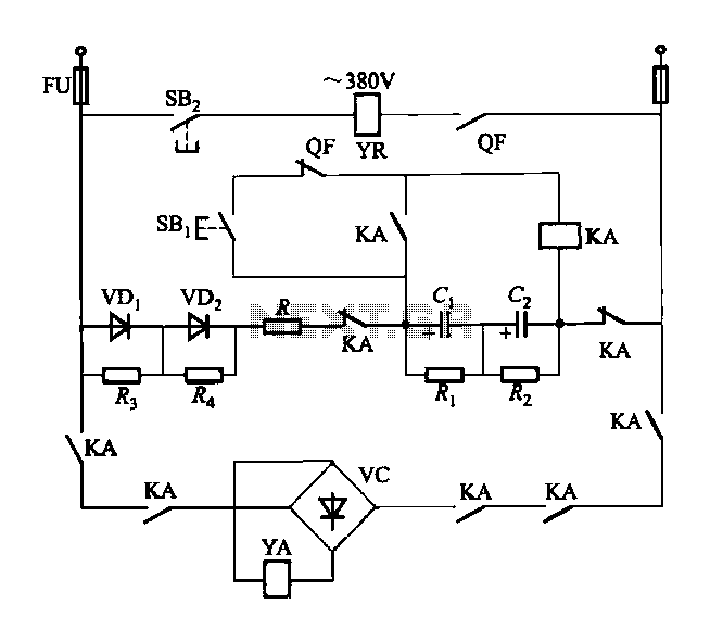
The DW15-200-630A breaker solenoid is a DC solenoid designed for short-time operation. The DK-1 control box utilizes an AC power switch to manage the electromagnet circuit, as depicted in Figure 6-7. The DK-1 type electromagnetic control box includes several...
This PC fan controller circuit is designed with discrete components to control 12V fans that consume less than 200mA. The specified component values in the circuit diagram ensure that the voltage will not drop below 7V. If the fan...
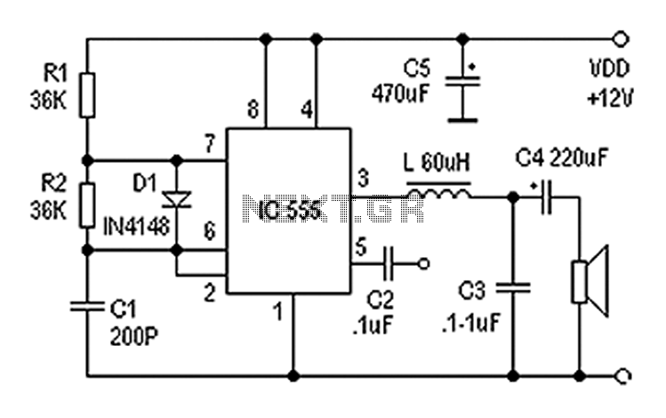
Also known as a digital amplifier, the Class-D amplifier is characterized by its compact size and high efficiency. This circuit utilizes a 555 timer IC to create a Class D amplifier. The 555 timer operates as a controllable multivibrator,...
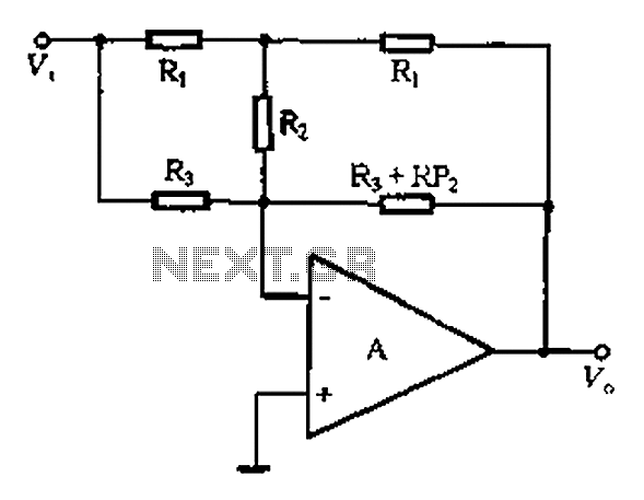
At high frequencies, the capacitor Cz can be considered a short circuit (i.e., the resistance of the RPi is negligible). This is illustrated in Figure 4-6 (a) of the apparatus, which corresponds to the equivalent circuit shown in Figure...