
Light Fence Security Alarm Circuit Schematic

The light fence security beeper circuit employs a phototransistor (T1) that acts as a light sensor, which is critical for detecting interruptions in the light path. The circuit is designed around the 4093 integrated circuit (IC1) configured as a low-frequency astable multivibrator. In its idle state, the circuit remains inactive as long as T1 is conducting, which occurs when it receives light from the green LED (D1). The phototransistor's conduction effectively disables the astable multivibrator, preventing the piezo buzzer from sounding.
When an object obstructs the light beam from D1, T1 stops conducting, which triggers IC1 to produce a low output signal. This transition activates the piezo buzzer, generating an audible alert. The frequency and duration of the beeping sound are influenced by the resistor-capacitor (RC) timing network formed by R3, R4, and C1, allowing for customization of the alarm's characteristics.
The circuit also includes a red LED (D2) that functions as a visual indicator, alerting users to the alarm's status. The design allows for the extension of the effective light path through the use of a reflector and lens assembly, enabling detection over distances of 1 to 2 meters with a high-brightness green LED. Alternatively, a laser pointer can be integrated into the setup, providing a more focused light source for enhanced detection capabilities.
Overall, this light fence security beeper circuit is a versatile and effective solution for various security applications, offering both auditory and visual alerts in response to unauthorized access or movement within a predefined area.A simple light fence security beeper is presented here. This circuit can be used as a door alarm, gate alarm, pathway alarm, etc. Any 12 Volt dc power supply can power the whole circuit. Working of this circuit is straight forward. In standby mode photo transistor T1 receives light from the green LED (D1) and T1 conducts to disable the gated low-frequency astable built around IC1(4093). When this light path is interrupted by any object in the path, T1 stops conducting and IC1 is switched by the low level at its input point (pins 12&13). As a result the piezo-buzzer starts beeping at a slow rate determined by the in circuit values of R3, R4 & C1.
Red LED (D2) is a visual warning indicator. With the help of suitable reflector and lens assembly, length of the light path can be increased. A minimum of 1 to 2 metres is possible with a high-bright green LED as D1. A laser pointer can also be used as the light source. 🔗 External reference
Related Circuits

A vibration sensor or piezoelectric vibration sensor circuit diagram. It emits a loud beep when an attempt is made to break a door or window. The alarm automatically ceases after three minutes. The circuit utilizes a piezo element as...
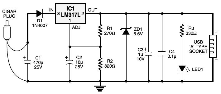
Cigar lighter plug to USB power socket. This circuit converts a 12V DC source from a car cigar lighter plug into a USB power socket with a 5V DC output. This circuit can be used to power 5V electronic...

This circuit is tested and functional. The LM389 integrated circuit serves as the core element, where the voice channel number is acquired by the microphone (MIC) and converted into electrical signals. These signals are amplified by the volume control...
If the audio input is a microphone, it is expected to precede an amplifier to achieve an output power of approximately 8W. The amateur seeking to enhance a small transmitter, which is likely already constructed, can utilize this circuit,...

The CMOS 4001 consists of four independent two-input NOR gates. These gates are organized into two pairs. Gates 1 and 2 are connected to form a latching circuit. When the alarm is triggered, they will latch and activate the...

The circuit is designed to connect in parallel with a telephone, displaying the dialed number using DTMF (Dual Tone Multi-Frequency) signaling. It can also show the number dialed from the receiving party's phone, making it useful for capturing numbers...