
transmitter circuits 4

The circuit described is a compact and efficient FM transmitter designed for audio applications, particularly suited for use with personal audio devices such as MP3 players. The circuit's architecture allows for straightforward assembly and tuning, making it accessible for amateur electronics enthusiasts. The use of a Philips LY89 transistor as the main amplifier component ensures reliable performance across the FM frequency range, while the integration of the MAX2606 chip simplifies the design by eliminating the need for additional coils and complex tuning mechanisms.
Key components of the circuit include variable capacitors for fine-tuning, inductors for signal conditioning, and carefully selected resistors to maintain circuit stability and performance. The choice of a USB power supply enhances the circuit's versatility, allowing for easy integration with common power sources. The inclusion of a common-mode choke further improves the circuit's robustness against potential interference, making it suitable for various applications, from home audio to automotive use.
In summary, the described FM transmitter circuit offers a balance of simplicity and functionality, allowing users to enjoy their music wirelessly while providing sufficient power output for effective transmission. Its design accommodates a range of applications, making it a valuable addition to any audio enthusiast's toolkit. Proper assembly and tuning will ensure optimal performance, delivering a reliable and enjoyable audio experience.If the audio input is a microphone it will be supposed precedes amplifier so that it acquires a force of order of 8W roughly. The amateur that wants it strengthens some small transmitter, that likely it has already it manufactured!
The present circuit can give force 25-30W, with cont rol no bigger than 4-5 W. As it appears in the analytic drawing, the amplifier is manufactured with the transistor TR1 of type ’LY89 of Phillips. The transistor this is specifically drawn for operation in frequencies up to 175 hz, with very good results.
His special characteristics appear below: Variable capacitors C1, C2, with inductor L1, constitute the coordinated circuit that adapts the exit of our transmitter in this amplifier RF. the circuit has been calculated suitably, so that it covers all band the FM with the biggest possible output.
Inductor RFC1 polarize the transistor, so as to it works in order C that is to say with the biggest output. Inductor L2 in the collector of TR1, constitutes the charge of amplifier, while RFC2 prevents the RF signals escape in the line of catering.
Capacitor C2 and resistance R1, protect the circuit from auto polarize. The coordinated circuit of expense that is constituted by inductor L2 and variable capacitors C3, C4, adapts the exit of amplifier RF with the next stage that can be some amplifier RF of high force (> 100W) or a aerial. The manufacture of amplifier is very simple and easy. Puncture the point PCB that will pass the nutshell of TR1. Stick the capacitors, variable, the resistance, the RF tsok and the inductors. Finally you stick the TR1, being careful not overheats at the welding and blend pin his. Clean finally PCB from the residues of soldering. Make a very careful control for by any chance errors, omissions, short-circuits, chills you stick also anything other that could you make wonder why does not work the amplifier.
If all they are it includes, you connect the exit of your transmitter (3-4W) in the entry of amplifier. The exit of amplifier him you will connect in some charge (dummy load) or in the aerial, through a bridge stagnant.
Be supplied with tendency 11-15V your amplifier. (Power supply it should it provides current 45th). Regulate the 4 variable (C1-C4, until you take the biggest force of expense. The amplifier is ready. The TK1 needs a wiper of dimensions 5x10cm for trouble free operation. This wiper screw in the TR1 without isolators, after his central screw has electric isolation from remainder pins. This MP3 Player FM transmitter can be used to listen to your own music throughout your home. The transmitter circuit use no coils that have to be wound. When this FM transmitter used in the car, there is no need for a separate input to the car stereo to play back the music files from your MP3 player.
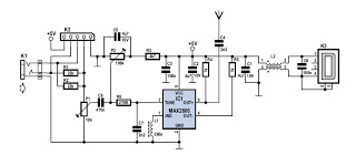
This FM transmitter use a chip made by Maxim Integrated Products, the MAX2606. The VCO (Voltage Controlled Oscillator) in this IC uses a Colpitts oscillator circuit. The variable-capacitance (varicap) diode and feedback capacitors for the tuning have also been integrated on this chip, so that you only need an external inductor to fix the central oscillator frequency. The supply voltage to the IC should be between 2. 7 and 5. 5 V, the current consumption is between 2 and 4 mA. With values like these it seemed a good idea to supply the circuit with power from a USB port. A common-mode choke is connected in series with the USB connections in order to avoid interference between the circuit and the PC supply.
The stereo signal connected to K1 is combined via R1 and R2 and is then passed via volume control P1 to the Tune input of IC1, where it causes the carrier wave to be frequency modulated. Filter R6/C7 is used to restrict the bandwidth of the audio signal. The setting of the frequency (across the whole VHF FM broadcast band) is done with P2, which is connected to
🔗 External reference
Related Circuits
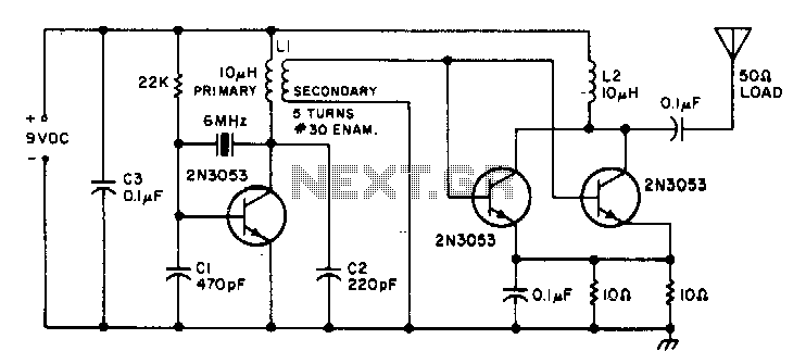
This is a small transmitter designed to fit inside a plastic Easter egg. It delivers approximately 1 W of measured RF output into a 50-ohm dummy load and does not generate any heating issues within the circuit. The crystal...
This application note explains how the transfer function of most operational amplifier circuits can be derived through a straightforward process of nodal analysis. The transfer function of operational amplifier (op amp) circuits is a critical aspect for understanding their behavior...
This continuous wave (CW) transmitter is capable of producing an output power of up to 3 watts. By applying a 24-volt supply to transistor Q2, the output power can be increased to as much as 10 watts. It is...
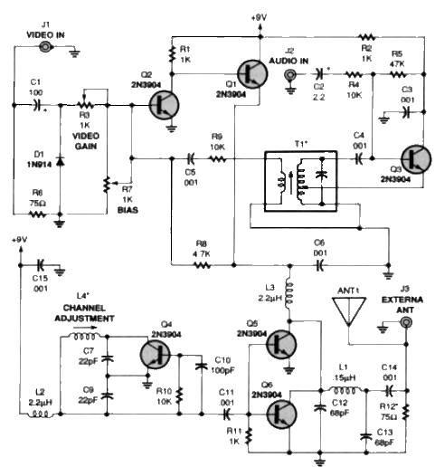
A simple TV audio-video transmitter circuit can be designed using this schematic diagram. This circuit can transmit video signals from a VCR or other devices to a TV without the need for cables. Video signals input at jack J1...
This MP3 player FM transmitter allows users to enjoy their music throughout their home. The transmitter circuit does not require any coils to be wound. When utilized in a vehicle, there is no need for a separate input to...

This is a transistor tester integrated into a circuit or printed circuit board (PCB). It is utilized when a project does not function correctly, allowing for the testing of electronic components. The transistor tester is a crucial tool in electronic...